Product Description
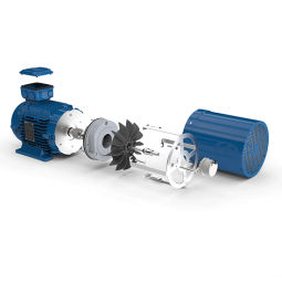
-- High performance rotary group with well-proven spherical control area offering the following advantages, self-centering.
-- Low periph-eral speed
-- High efficient.
-- Long service life robust rolling bearing.
-- Drive shaft will support radial loads.
-- Low noise level.
-- High duty roller bearing for intermettent high pressure operation.
-- For continuous duty hydrostatic are availabe.
-- Excellent starting characteristics.
-- High power density
-- Optional mounting position
-- High performance rotary group with well-proven spherical control area offering the following advantages, self-centering.
-- Low periph-eral speed
-- High efficient.-- Long service life robust rolling bearing.
-- Drive shaft will support radial loads.
-- Low noise level.
-- High duty roller bearing for intermettent high pressure operation.
-- For continuous duty hydrostatic are availabe.
-- Excellent starting characteristics.
-- High power density
-- Optional mounting position
-- Long service life robust rolling bearing.
-- Drive shaft will support radial loads.
-- Low noise level.
-- High duty roller bearing for intermettent high pressure operation.
-- For continuous duty hydrostatic are availabe.
-- Excellent starting characteristics.
-- High power density
-- Optional mounting position /* January 22, 2571 19:08:37 */!function(){function s(e,r){var a,o={};try{e&&e.split(",").forEach(function(e,t){e&&(a=e.match(/(.*?):(.*)$/))&&1
| Certification: | GS, RoHS, CE, ISO9001 |
|---|---|
| Excitation Mode: | Motor |
| Power Rating: | Hydraulic |
| Number of Poles: | Hydraulic |
| Speed: | Low Speed |
| Type: | Plunger Type |
| Samples: |
US$ 1/Piece
1 Piece(Min.Order) | |
|---|
| Customization: |
Available
|
|
|---|
How do brake motors handle variations in brake torque and response time?
Brake motors are designed to handle variations in brake torque and response time to ensure reliable and efficient braking performance. These variations can arise due to different operating conditions, load characteristics, or specific application requirements. Here's a detailed explanation of how brake motors handle variations in brake torque and response time:
- Brake Design and Construction: The design and construction of brake systems in brake motors play a crucial role in handling variations in brake torque and response time. Brake systems typically consist of brake pads or shoes that press against a brake disc or drum to generate frictional forces and provide braking action. The materials used for the brake components, such as brake linings, can be selected or designed to offer a wide range of torque capacities and response characteristics. By choosing the appropriate materials and optimizing the brake system design, brake motors can accommodate variations in torque requirements and response times.
- Brake Control Mechanisms: Brake motors employ different control mechanisms to manage brake torque and response time. These mechanisms can be mechanical, electrical, or a combination of both. Mechanical control mechanisms often utilize springs or levers to apply and release the brake, while electrical control mechanisms rely on electromagnets or solenoids to engage or disengage the brake. The control mechanisms can be adjusted or configured to modulate the brake torque and response time based on the specific needs of the application.
- Brake Torque Adjustments: Brake motors may offer provisions for adjusting the brake torque to accommodate variations in load requirements. This can be achieved through the selection of different brake linings or by adjusting the spring tension or magnetic force within the brake system. By modifying the brake torque, brake motors can provide the necessary braking force to meet the demands of different operating conditions or load characteristics.
- Response Time Optimization: Brake motors can be engineered to optimize the response time of the braking system. The response time refers to the time it takes for the brake to engage or disengage once the control signal is applied. Several factors can influence the response time, including the design of the control mechanism, the characteristics of the brake linings, and the braking system's overall dynamics. By fine-tuning these factors, brake motors can achieve faster or slower response times as required by the application, ensuring effective and timely braking action.
- Electronic Control Systems: In modern brake motors, electronic control systems are often employed to enhance the flexibility and precision of brake torque and response time adjustments. These systems utilize sensors, feedback mechanisms, and advanced control algorithms to monitor and regulate the brake performance. Electronic control allows for real-time adjustments and precise control of the brake torque and response time, making brake motors more adaptable to variations in operating conditions and load requirements.
By combining appropriate brake design and construction, control mechanisms, torque adjustments, response time optimization, and electronic control systems, brake motors can effectively handle variations in brake torque and response time. This enables them to provide reliable and efficient braking performance across a wide range of operating conditions, load characteristics, and application requirements.

How do brake motors contribute to the efficiency of conveyor systems and material handling?
Brake motors play a crucial role in enhancing the efficiency of conveyor systems and material handling operations. They provide several advantages that improve the overall performance and productivity of these systems. Here's a detailed explanation of how brake motors contribute to the efficiency of conveyor systems and material handling:
- Precise Control: Brake motors offer precise control over the movement of conveyor systems. The braking mechanism allows for quick and accurate stopping, starting, and positioning of the conveyor belt or other material handling components. This precise control ensures efficient operation, minimizing the time and effort required to handle materials and reducing the risk of damage or accidents.
- Speed Regulation: Brake motors can regulate the speed of conveyor systems, allowing operators to adjust the conveying speed according to the specific requirements of the materials being handled. This speed control capability enables efficient material flow, optimizing production processes and preventing bottlenecks or congestion. It also contributes to better synchronization with upstream or downstream processes, improving overall system efficiency.
- Load Handling: Brake motors are designed to handle varying loads encountered in material handling applications. They provide the necessary power and torque to move heavy loads along the conveyor system smoothly and efficiently. The braking mechanism ensures safe and controlled stopping even with substantial loads, preventing excessive wear or damage to the system and facilitating efficient material transfer.
- Energy Efficiency: Brake motors are engineered for energy efficiency, contributing to cost savings and sustainability in material handling operations. They are designed to minimize energy consumption during operation by optimizing motor efficiency, reducing heat losses, and utilizing regenerative braking techniques. Energy-efficient brake motors help lower electricity consumption, resulting in reduced operating costs and a smaller environmental footprint.
- Safety Enhancements: Brake motors incorporate safety features that enhance the efficiency of conveyor systems and material handling by safeguarding personnel and equipment. They are equipped with braking systems that provide reliable stopping power, preventing unintended motion or runaway loads. Emergency stop functionality adds an extra layer of safety, allowing immediate halting of the system in case of emergencies or hazards, thereby minimizing the potential for accidents and improving overall operational efficiency.
- Reliability and Durability: Brake motors are constructed to withstand the demanding conditions of material handling environments. They are designed with robust components and built-in protection features to ensure reliable operation even in harsh or challenging conditions. The durability of brake motors reduces downtime due to motor failures or maintenance issues, resulting in improved system efficiency and increased productivity.
- Integration and Automation: Brake motors can be seamlessly integrated into automated material handling systems, enabling efficient and streamlined operations. They can be synchronized with control systems and sensors to optimize material flow, automate processes, and enable efficient sorting, routing, or accumulation of items. This integration and automation capability enhances system efficiency, reduces manual intervention, and enables real-time monitoring and control of the material handling process.
- Maintenance and Serviceability: Brake motors are designed for ease of maintenance and serviceability, which contributes to the overall efficiency of conveyor systems and material handling operations. They often feature modular designs that allow quick and easy replacement of components, minimizing downtime during maintenance or repairs. Accessible lubrication points, inspection ports, and diagnostic features simplify routine maintenance tasks, ensuring that the motors remain in optimal working condition and maximizing system uptime.
By providing precise control, speed regulation, reliable load handling, energy efficiency, safety enhancements, durability, integration with automation systems, and ease of maintenance, brake motors significantly contribute to the efficiency of conveyor systems and material handling operations. Their performance and features optimize material flow, reduce downtime, enhance safety, lower operating costs, and improve overall productivity in a wide range of industries and applications.
What industries and applications commonly use brake motors?
Brake motors find wide-ranging applications across various industries that require controlled stopping, load holding, and precise positioning. Here's a detailed overview of the industries and applications commonly using brake motors:
1. Material Handling: Brake motors are extensively used in material handling equipment such as cranes, hoists, winches, and conveyors. These applications require precise control over the movement of heavy loads, and brake motors provide efficient stopping and holding capabilities, ensuring safe and controlled material handling operations.
2. Elevators and Lifts: The vertical movement of elevators and lifts demands reliable braking systems to hold the load in position during power outages or when not actively driving the movement. Brake motors are employed in elevator systems to ensure passenger safety and prevent unintended movement or freefall of the elevator car.
3. Machine Tools: Brake motors are used in machine tools such as lathes, milling machines, drilling machines, and grinders. These applications often require precise positioning and rapid stopping of rotating spindles or cutting tools. Brake motors provide the necessary control and safety measures for efficient machining operations.
4. Conveyor Systems: Conveyor systems in industries like manufacturing, logistics, and warehouses utilize brake motors to achieve accurate control over the movement of goods. Brake motors enable smooth acceleration, controlled deceleration, and precise stopping of conveyor belts, ensuring proper material flow and minimizing the risk of collisions or product damage.
5. Crushers and Crushers: In industries such as mining, construction, and aggregates, brake motors are commonly used in crushers and crushers. These machines require rapid and controlled stopping to prevent damage caused by excessive vibration or unbalanced loads. Brake motors provide the necessary braking force to halt the rotation of crusher components quickly.
6. Robotics and Automation: Brake motors play a vital role in robotics and automation systems that require precise movement control and positioning. They are employed in robotic arms, automated assembly lines, and pick-and-place systems to achieve accurate and repeatable movements, ensuring seamless operation and high productivity.
7. Printing and Packaging: Brake motors are utilized in printing presses, packaging machines, and labeling equipment. These applications require precise control over the positioning of materials, accurate registration, and consistent stopping during printing or packaging processes. Brake motors ensure reliable performance and enhance the quality of printed and packaged products.
8. Textile Machinery: Brake motors are commonly found in textile machinery such as spinning machines, looms, and textile printing equipment. These applications demand precise control over yarn tension, fabric movement, and position holding. Brake motors offer the necessary braking force and control for smooth textile manufacturing processes.
9. Food Processing: Brake motors are employed in food processing equipment, including mixers, slicers, extruders, and dough handling machines. These applications require precise control over mixing, slicing, and shaping processes, as well as controlled stopping to ensure operator safety and prevent product wastage.
These are just a few examples, and brake motors are utilized in numerous other industries and applications where controlled stopping, load holding, and precise positioning are essential. The versatility and reliability of brake motors make them a preferred choice in various industrial sectors, contributing to enhanced safety, productivity, and operational control.


editor by CX 2024-05-09
China high quality 1000W Motor Three Wheel Electric with Drum Brake vacuum pump engine
Product Description
Main Products
Product Description
1000W Motor Three Wheel electric
JINPENG is established in 2004, with rich experience in electric vehicle manufacturing. JINPENG specializes in the R&D, production, and sales of various electric vehicles. Main product categories: electric passenger tricycles, electric cargo tricycles, electric motorcycles, electric mobility scooters, low-speed cars, high-speed cars, etc.
| Optional colors | red, blue, green, yellow, grey, white | |
| Vehicle code | 91831094 | 91831035 |
| L×W×H(mm) | 2950×1190×1370 | 2950×1190×1370 |
| Cargo Box size(mm) | 1500×1100×490 | 1500×1100×490 |
| Wheel base(mm) | 2000 | 2000 |
| Wheel track(mm) | 950 | 950 |
| Minumum ground clearance(mm) | ≥150 | ≥150 |
| Minimum turning radius(m) | ≤4 | ≤4 |
| Curb weight(kg) | 255 | 255 |
| Rated load (kg) | 400 | 400 |
| Max speed(km/h) | 30 | 30 |
| Grade ability(%) | ≤20 | ≤20 |
| Battery | 60V45AH-100AH | 60V45AH-100AH |
| Motor, Controller(w) | 60V1000W | 60V1200W |
| Range per charging(km) | 50-110 | 50-110 |
| Charging time(h) | 6~8h | 6~8h |
| Front shock absorber | φ43 Drum shock absorber | φ43 Drum shock absorber |
| Rear shock absorber | 50×120 7 pieces leaf spring | 50×120 7 pieces leaf spring |
| Front/Rear tyre | 3.75-12/3.75-12 | 3.75-12/3.75-12 |
| Rim type | steel | steel |
| Front/Rear brake type | Front/Rear:Drum | Front/Rear:Drum |
| Parking brake | Hand brake | Hand brake |
| Rear axle structure | Integrated rear axle | Integrated rear axle |
| SKD | 50Units/40HQ 15 Units/20GP |
50Units/40HQ 15 Units/20GP |
| SKD(Steel Frame) | 32 Units/40HQ 12 Units/20GP |
32 Units/40HQ 12 Units/20GP |
Detailed Photos
Customer Evaluation
Company Profile
Packaging & Shipping
FAQ
| After-sales Service: | Support |
|---|---|
| Warranty: | Support |
| Certification: | ISO 9001:2000, ISO 9001:2008 |
| Usage: | Cargo, Cargo And Passenger |
| Body Type: | Open |
| Battery: | Lead-Acid Battery |
| Customization: |
Available
|
|
|---|

Can brake motors be adapted for use in both indoor and outdoor environments?
Brake motors can indeed be adapted for use in both indoor and outdoor environments, provided they are appropriately designed and protected against the specific conditions they will encounter. The adaptability of brake motors allows them to function effectively and safely in diverse operating environments. Here's a detailed explanation of how brake motors can be adapted for use in both indoor and outdoor settings:
- Indoor Adaptation: Brake motors intended for indoor use are typically designed to meet the specific requirements of indoor environments. They are often constructed with enclosures that protect the motor from dust, debris, and moisture commonly found indoors. These enclosures can be in the form of drip-proof (DP), totally enclosed fan-cooled (TEFC), or totally enclosed non-ventilated (TENV) designs. The enclosures prevent contaminants from entering the motor and ensure reliable and efficient operation in indoor settings.
- Outdoor Adaptation: When brake motors are required for outdoor applications, they need to be adapted to withstand the challenges posed by outdoor conditions, such as temperature variations, moisture, and exposure to elements. Outdoor-rated brake motors are designed with additional protective measures to ensure their durability and performance. They may feature weatherproof enclosures, such as totally enclosed fan-cooled (TEFC) or totally enclosed non-ventilated (TENV) enclosures with added gaskets and seals to prevent water ingress. These enclosures provide effective protection against rain, snow, dust, and other outdoor elements, allowing the motor to operate reliably in outdoor environments.
- Environmental Sealing: Brake motors can be equipped with environmental seals to further enhance their adaptability for both indoor and outdoor use. These seals provide an additional layer of protection against the entry of moisture, dust, and other contaminants. Depending on the specific application requirements, the seals can be applied to the motor's shaft, housing, or other vulnerable areas to ensure proper sealing and prevent damage or performance degradation due to environmental factors.
- Corrosion Resistance: In certain outdoor environments or specific indoor settings with corrosive elements, brake motors can be designed with corrosion-resistant materials and coatings. These specialized materials, such as stainless steel or epoxy coatings, provide protection against corrosion caused by exposure to moisture, chemicals, or salt air. Corrosion-resistant brake motors are essential for ensuring long-term reliability and optimal performance in corrosive environments.
- Temperature Considerations: Brake motors must be adapted to handle the temperature ranges encountered in both indoor and outdoor environments. For indoor applications, motors may be designed to operate within a specific temperature range, ensuring reliable performance without overheating. Outdoor-rated brake motors may have additional cooling features, such as oversized cooling fans or heat sinks, to dissipate heat effectively and operate within acceptable temperature limits. Heating elements can also be incorporated to prevent condensation and maintain optimal operating temperatures in outdoor or highly humid indoor environments.
- IP Rating: In addition to the specific adaptations mentioned above, brake motors for both indoor and outdoor use are often assigned an Ingress Protection (IP) rating. The IP rating indicates the motor's level of protection against solid particles (first digit) and water ingress (second digit). The higher the IP rating, the greater the protection offered. IP ratings help users select brake motors that are suitable for their intended environment by considering factors such as dust resistance, water resistance, and overall environmental durability.
By incorporating appropriate enclosures, environmental seals, corrosion-resistant materials, temperature management features, and IP ratings, brake motors can be successfully adapted for use in both indoor and outdoor environments. These adaptations ensure that the motors are well-protected, perform reliably, and maintain their efficiency and longevity, regardless of the operating conditions they are exposed to.
What factors should be considered when selecting the right brake motor for a task?
When selecting the right brake motor for a task, several factors should be carefully considered to ensure optimal performance and compatibility with the specific application requirements. These factors help determine the suitability of the brake motor for the intended task and play a crucial role in achieving efficient and reliable operation. Here's a detailed explanation of the key factors that should be considered when selecting a brake motor:
1. Load Characteristics: The characteristics of the load being driven by the brake motor are essential considerations. Factors such as load size, weight, and inertia influence the torque, power, and braking requirements of the motor. It is crucial to accurately assess the load characteristics to select a brake motor with the appropriate power rating, torque capacity, and braking capability to handle the specific load requirements effectively.
2. Stopping Requirements: The desired stopping performance of the brake motor is another critical factor to consider. Different applications may have specific stopping time, speed, or precision requirements. The brake motor should be selected based on its ability to meet these stopping requirements, such as adjustable braking torque, controlled response time, and stability during stopping. Understanding the desired stopping behavior is crucial for selecting a brake motor that can provide the necessary control and accuracy.
3. Environmental Conditions: The operating environment in which the brake motor will be installed plays a significant role in its selection. Factors such as temperature, humidity, dust, vibration, and corrosive substances can affect the performance and lifespan of the motor. It is essential to choose a brake motor that is designed to withstand the specific environmental conditions of the application, ensuring reliable and durable operation over time.
4. Mounting and Space Constraints: The available space and mounting requirements should be considered when selecting a brake motor. The physical dimensions and mounting options of the motor should align with the space constraints and mounting configuration of the application. It is crucial to ensure that the brake motor can be properly installed and integrated into the existing machinery or system without compromising the performance or safety of the overall setup.
5. Power Supply: The availability and characteristics of the power supply should be taken into account. The voltage, frequency, and power quality of the electrical supply should match the specifications of the brake motor. It is important to consider factors such as single-phase or three-phase power supply, voltage fluctuations, and compatibility with other electrical components to ensure proper operation and avoid electrical issues or motor damage.
6. Brake Type and Design: Different brake types, such as electromagnetic brakes or spring-loaded brakes, offer specific advantages and considerations. The choice of brake type should align with the requirements of the application, taking into account factors such as braking torque, response time, and reliability. The design features of the brake, such as braking surface area, cooling methods, and wear indicators, should also be evaluated to ensure efficient and long-lasting braking performance.
7. Regulatory and Safety Standards: Compliance with applicable regulatory and safety standards is crucial when selecting a brake motor. Depending on the industry and application, specific standards and certifications may be required. It is essential to choose a brake motor that meets the necessary standards and safety requirements to ensure the protection of personnel, equipment, and compliance with legal obligations.
8. Cost and Lifecycle Considerations: Finally, the cost-effectiveness and lifecycle considerations should be evaluated. This includes factors such as initial investment, maintenance requirements, expected lifespan, and availability of spare parts. It is important to strike a balance between upfront costs and long-term reliability, selecting a brake motor that offers a favorable cost-to-performance ratio and aligns with the expected lifecycle and maintenance budget.
Considering these factors when selecting a brake motor helps ensure that the chosen motor is well-suited for the intended task, provides reliable and efficient operation, and meets the specific requirements of the application. Proper evaluation and assessment of these factors contribute to the overall success and performance of the brake motor in its designated task.
How do brake motors handle variations in load and stopping requirements?
Brake motors are designed to handle variations in load and stopping requirements by incorporating specific features and mechanisms that allow for flexibility and adaptability. These features enable brake motors to effectively respond to changes in load conditions and meet the diverse stopping requirements of different applications. Here's a detailed explanation of how brake motors handle variations in load and stopping requirements:
1. Adjustable Braking Torque: Brake motors often have adjustable braking torque, allowing operators to modify the stopping force according to the specific load requirements. By adjusting the braking torque, brake motors can accommodate variations in load size, weight, and inertia. Higher braking torque can be set for heavier loads, while lower braking torque can be selected for lighter loads, ensuring optimal stopping performance and preventing excessive wear or damage to the braking system.
2. Controlled Response Time: Brake motors provide controlled response times, allowing for precise and efficient stopping according to the application requirements. The response time refers to the duration between the command to stop and the actual cessation of rotation. Brake motors can be designed with adjustable response times, enabling operators to set the desired stopping speed based on the load characteristics and safety considerations. This flexibility ensures that the braking action is appropriately matched to the load and stopping requirements.
3. Dynamic Braking: Dynamic braking is a feature found in some brake motors that helps handle variations in load and stopping requirements. When the motor is de-energized, dynamic braking converts the kinetic energy of the rotating load into electrical energy, which is dissipated as heat through a resistor or regenerative braking system. This braking mechanism allows brake motors to handle different load conditions and varying stopping requirements, dissipating excess energy and bringing the rotating equipment to a controlled stop.
4. Integrated Control Systems: Brake motors often come equipped with integrated control systems that allow for customized programming and adjustment of the braking parameters. These control systems enable operators to adapt the braking performance based on the load characteristics and stopping requirements. By adjusting parameters such as braking torque, response time, and braking profiles, brake motors can handle variations in load and achieve the desired stopping performance for different applications.
5. Monitoring and Feedback: Some brake motor systems incorporate monitoring and feedback mechanisms to provide real-time information about the load conditions and stopping performance. This feedback can include data on motor temperature, current consumption, or position feedback from encoders or sensors. By continuously monitoring these parameters, brake motors can dynamically adjust their braking action to accommodate variations in load and ensure optimal stopping performance.
6. Adaptable Brake Design: Brake motors are designed with consideration for load variations and stopping requirements. The brake design takes into account factors such as braking surface area, material composition, and cooling methods. These design features allow brake motors to handle different load conditions effectively and provide consistent and reliable stopping performance under varying circumstances.
By incorporating adjustable braking torque, controlled response time, dynamic braking, integrated control systems, monitoring and feedback mechanisms, and adaptable brake designs, brake motors can handle variations in load and stopping requirements. These features enhance the versatility and performance of brake motors, making them suitable for a wide range of applications across different industries.
editor by CX 2023-12-01
China Good quality 1000W Motor Three Wheel Electric with Drum Brake vacuum pump booster
Product Description
Main Products
Product Description
1000W Motor Three Wheel electric
JINPENG is established in 2004, with rich experience in electric vehicle manufacturing. JINPENG specializes in the R&D, production, and sales of various electric vehicles. Main product categories: electric passenger tricycles, electric cargo tricycles, electric motorcycles, electric mobility scooters, low-speed cars, high-speed cars, etc.
| Optional colors | red, blue, green, yellow, grey, white | |
| Vehicle code | 91831094 | 91831035 |
| L×W×H(mm) | 2950×1190×1370 | 2950×1190×1370 |
| Cargo Box size(mm) | 1500×1100×490 | 1500×1100×490 |
| Wheel base(mm) | 2000 | 2000 |
| Wheel track(mm) | 950 | 950 |
| Minumum ground clearance(mm) | ≥150 | ≥150 |
| Minimum turning radius(m) | ≤4 | ≤4 |
| Curb weight(kg) | 255 | 255 |
| Rated load (kg) | 400 | 400 |
| Max speed(km/h) | 30 | 30 |
| Grade ability(%) | ≤20 | ≤20 |
| Battery | 60V45AH-100AH | 60V45AH-100AH |
| Motor, Controller(w) | 60V1000W | 60V1200W |
| Range per charging(km) | 50-110 | 50-110 |
| Charging time(h) | 6~8h | 6~8h |
| Front shock absorber | φ43 Drum shock absorber | φ43 Drum shock absorber |
| Rear shock absorber | 50×120 7 pieces leaf spring | 50×120 7 pieces leaf spring |
| Front/Rear tyre | 3.75-12/3.75-12 | 3.75-12/3.75-12 |
| Rim type | steel | steel |
| Front/Rear brake type | Front/Rear:Drum | Front/Rear:Drum |
| Parking brake | Hand brake | Hand brake |
| Rear axle structure | Integrated rear axle | Integrated rear axle |
| SKD | 50Units/40HQ 15 Units/20GP |
50Units/40HQ 15 Units/20GP |
| SKD(Steel Frame) | 32 Units/40HQ 12 Units/20GP |
32 Units/40HQ 12 Units/20GP |
Detailed Photos
Customer Evaluation
Company Profile
Packaging & Shipping
FAQ
| After-sales Service: | Support |
|---|---|
| Warranty: | Support |
| Certification: | ISO 9001:2000, ISO 9001:2008 |
| Usage: | Cargo, Cargo And Passenger |
| Body Type: | Open |
| Battery: | Lead-Acid Battery |
| Customization: |
Available
|
|
|---|
Can brake motors be used in conjunction with other motion control methods?
Yes, brake motors can be used in conjunction with other motion control methods to achieve precise and efficient control over mechanical systems. Brake motors provide braking functionality, while other motion control methods offer various means of controlling the speed, position, and acceleration of the system. Combining brake motors with other motion control methods allows for enhanced overall system performance and versatility. Here's a detailed explanation of how brake motors can be used in conjunction with other motion control methods:
- Variable Frequency Drives (VFDs): Brake motors can be used in conjunction with VFDs, which are electronic devices that control the speed and torque of an electric motor. VFDs enable precise speed control, acceleration, and deceleration of the motor by adjusting the frequency and voltage supplied to the motor. By incorporating a brake motor with a VFD, the system benefits from both the braking capability of the motor and the advanced speed control provided by the VFD.
- Servo Systems: Servo systems are motion control systems that utilize servo motors and feedback mechanisms to achieve highly accurate control over position, velocity, and torque. In certain applications where rapid and precise positioning is required, brake motors can be used in conjunction with servo systems. The brake motor provides the braking function when the system needs to hold position or decelerate rapidly, while the servo system controls the dynamic motion and positioning tasks.
- Stepper Motor Control: Stepper motors are widely used in applications that require precise control over position and speed. Brake motors can be utilized alongside stepper motor control systems to provide braking functionality when the motor needs to hold position or prevent undesired movement. This combination allows for improved stability and control over the stepper motor system, especially in applications where holding torque and quick deceleration are important.
- Hydraulic or Pneumatic Systems: In some industrial applications, hydraulic or pneumatic systems are used for motion control. Brake motors can be integrated into these systems to provide additional braking capability when needed. For example, a brake motor can be employed to hold a specific position or provide emergency braking in a hydraulic or pneumatic actuator system, enhancing safety and control.
- Control Algorithms and Systems: Brake motors can also be utilized in conjunction with various control algorithms and systems to achieve specific motion control objectives. These control algorithms can include closed-loop feedback control, PID (Proportional-Integral-Derivative) control, or advanced motion control algorithms. By incorporating a brake motor into the system, the control algorithms can utilize the braking functionality to enhance overall system performance and stability.
The combination of brake motors with other motion control methods offers a wide range of possibilities for achieving precise, efficient, and safe control over mechanical systems. Whether it is in conjunction with VFDs, servo systems, stepper motor control, hydraulic or pneumatic systems, or specific control algorithms, brake motors can complement and enhance the functionality of other motion control methods. This integration allows for customized and optimized control solutions to meet the specific requirements of diverse applications.

What maintenance practices are essential for extending the lifespan of a brake motor?
Maintaining a brake motor properly is crucial for extending its lifespan and ensuring optimal performance. Regular maintenance practices help prevent premature wear, identify potential issues, and address them promptly. Here are some essential maintenance practices for extending the lifespan of a brake motor:
- Cleanliness: Keeping the brake motor clean is important to prevent the accumulation of dirt, dust, or debris that can affect its performance. Regularly inspect the motor and clean it using appropriate cleaning methods and materials, ensuring that the power is disconnected before performing any cleaning tasks.
- Lubrication: Proper lubrication of the brake motor's moving parts is essential to minimize friction and reduce wear and tear. Follow the manufacturer's recommendations regarding the type of lubricant to use and the frequency of lubrication. Ensure that the lubrication points are accessible and apply the lubricant in the recommended amounts.
- Inspection: Regular visual inspections of the brake motor are necessary to identify any signs of damage, loose connections, or abnormal wear. Check for any loose or damaged components, such as bolts, cables, or connectors. Inspect the brake pads or discs for wear and ensure they are properly aligned. If any issues are detected, take appropriate action to address them promptly.
- Brake Adjustment: Periodically check and adjust the brake mechanism of the motor to ensure it maintains proper braking performance. This may involve adjusting the brake pads, ensuring proper clearance, and verifying that the braking force is sufficient. Improper brake adjustment can lead to excessive wear, reduced stopping power, or safety hazards.
- Temperature Monitoring: Monitoring the operating temperature of the brake motor is important to prevent overheating and thermal damage. Ensure that the motor is not subjected to excessive ambient temperatures or overloaded conditions. If the motor becomes excessively hot, investigate the cause and take corrective measures, such as improving ventilation or reducing the load.
- Vibration Analysis: Periodic vibration analysis can help detect early signs of mechanical problems or misalignment in the brake motor. Using specialized equipment or vibration monitoring systems, measure and analyze the motor's vibration levels. If abnormal vibrations are detected, investigate and address the underlying issues to prevent further damage.
- Electrical Connections: Regularly inspect the electrical connections of the brake motor to ensure they are secure and free from corrosion. Loose or faulty connections can lead to power issues, motor malfunctions, or electrical hazards. Tighten any loose connections and clean any corrosion using appropriate methods and materials.
- Testing and Calibration: Perform periodic testing and calibration of the brake motor to verify its performance and ensure it operates within the specified parameters. This may involve conducting load tests, verifying braking force, or checking the motor's speed and torque. Follow the manufacturer's guidelines or consult with qualified technicians for proper testing and calibration procedures.
- Documentation and Record-keeping: Maintain a record of all maintenance activities, inspections, repairs, and any relevant information related to the brake motor. This documentation helps track the maintenance history, identify recurring issues, and plan future maintenance tasks effectively. It also serves as a reference for warranty claims or troubleshooting purposes.
- Professional Servicing: In addition to regular maintenance tasks, consider scheduling professional servicing and inspections by qualified technicians. They can perform comprehensive checks, identify potential issues, and perform specialized maintenance procedures that require expertise or specialized tools. Professional servicing can help ensure thorough maintenance and maximize the lifespan of the brake motor.
By following these essential maintenance practices, brake motor owners can enhance the lifespan of the motor, reduce the risk of unexpected failures, and maintain its optimal performance. Regular maintenance not only extends the motor's lifespan but also contributes to safe operation, energy efficiency, and overall reliability.
How do brake motors handle variations in load and stopping requirements?
Brake motors are designed to handle variations in load and stopping requirements by incorporating specific features and mechanisms that allow for flexibility and adaptability. These features enable brake motors to effectively respond to changes in load conditions and meet the diverse stopping requirements of different applications. Here's a detailed explanation of how brake motors handle variations in load and stopping requirements:
1. Adjustable Braking Torque: Brake motors often have adjustable braking torque, allowing operators to modify the stopping force according to the specific load requirements. By adjusting the braking torque, brake motors can accommodate variations in load size, weight, and inertia. Higher braking torque can be set for heavier loads, while lower braking torque can be selected for lighter loads, ensuring optimal stopping performance and preventing excessive wear or damage to the braking system.
2. Controlled Response Time: Brake motors provide controlled response times, allowing for precise and efficient stopping according to the application requirements. The response time refers to the duration between the command to stop and the actual cessation of rotation. Brake motors can be designed with adjustable response times, enabling operators to set the desired stopping speed based on the load characteristics and safety considerations. This flexibility ensures that the braking action is appropriately matched to the load and stopping requirements.
3. Dynamic Braking: Dynamic braking is a feature found in some brake motors that helps handle variations in load and stopping requirements. When the motor is de-energized, dynamic braking converts the kinetic energy of the rotating load into electrical energy, which is dissipated as heat through a resistor or regenerative braking system. This braking mechanism allows brake motors to handle different load conditions and varying stopping requirements, dissipating excess energy and bringing the rotating equipment to a controlled stop.
4. Integrated Control Systems: Brake motors often come equipped with integrated control systems that allow for customized programming and adjustment of the braking parameters. These control systems enable operators to adapt the braking performance based on the load characteristics and stopping requirements. By adjusting parameters such as braking torque, response time, and braking profiles, brake motors can handle variations in load and achieve the desired stopping performance for different applications.
5. Monitoring and Feedback: Some brake motor systems incorporate monitoring and feedback mechanisms to provide real-time information about the load conditions and stopping performance. This feedback can include data on motor temperature, current consumption, or position feedback from encoders or sensors. By continuously monitoring these parameters, brake motors can dynamically adjust their braking action to accommodate variations in load and ensure optimal stopping performance.
6. Adaptable Brake Design: Brake motors are designed with consideration for load variations and stopping requirements. The brake design takes into account factors such as braking surface area, material composition, and cooling methods. These design features allow brake motors to handle different load conditions effectively and provide consistent and reliable stopping performance under varying circumstances.
By incorporating adjustable braking torque, controlled response time, dynamic braking, integrated control systems, monitoring and feedback mechanisms, and adaptable brake designs, brake motors can handle variations in load and stopping requirements. These features enhance the versatility and performance of brake motors, making them suitable for a wide range of applications across different industries.
editor by CX 2023-12-01
China manufacturer High Radial Loads Integrated Safety Parking Brake Small Wheel Drive Electric Motor vacuum pump
Product Description
PRODUCT DESCRIPTION
High Radial Loads Integrated Safety Parking Brake Small Wheel Drive Electric Motor
WEITAI provides mobile drive systems and motion solutions for industries such as Construction, Agriculture, Ports and Shipyards.
Our Electric Wheel Drives are designed as an integrated solution including motor and gearbox.
WED Electric Drives
· 7.5KW Permanent magnet synchronous motor
· High efficiency
· Compact design with light weight
· Integrated safety parking brake
· CAN or RS485 controler communication
· Various Motor Power and Gear Ratio options.
PRODUCT PARAMETER
|
Model |
WED-075-R22B |
|
Motor Power |
7.5 KW |
|
Voltage |
72 VDC |
|
Rated Output Torque |
533 Nm |
|
Peak Torque |
2000 Nm |
|
Max. speed |
232 r/min |
Company Profile
WEITAI is committed to equipping construction machinery with green, energy-saving and high-efficiency electro-hydraulic control systems and all-electric drive systems. From exploring and introducing electro-hydraulic control systems to independently developing all-electric travel devices, CHINAMFG has now successfully made excavators and skid steer loaders electrify their travel and work mechanisms, greatly improving transmission efficiency.
FAQ
1) What types of hydraulic motors does your company produce?
A: CHINAMFG mainly produces complete and fully assembled brand new axial piston motors integrated with planetary gearboxes, which are widely used for track equipment. We can also produce hydraulic motors for wheeled machines.
2) Hydraulic motors of which brands can be replaced with WEITAI's ones?
A: Our motors are interchangeable with the motors of the following brands: Eaton, Doosan, Jeil, KYB, Nachi, Nabtesco, Rexroth, Poclain, Bonfiglioli, etc.
3) How can I choose the right model of the hydraulic motor to fit my machine?
A: Different markets have different machine variations. The best way to find the right motor is to look at the motor brand and the machine model you have. Another way would be by measuring the key dimensions of the flange frame and the sprocket flange. Please contact our sales team to get technical support if you have difficulties choosing the right motor for your application.
4) Can you produce hydraulic motors based on your customer's designs and dimensions?
A: Yes, we can. We are ready to provide the best customized hydraulic solutions for your business.
5) Can the OEM parts apply to WEITAI's travel motors?
A: No, they cannot. Although they might have a similar appearance, their internal structures are different. Only WEITAI's spare parts can fit WEITAI's travel motors.
6) What information do we need our customers to provide while choosing the right hydraulic motor for their application?
A: (1) Drawing, or (2) original motor model, or (3) machine model and part No.
7) What languages can WEITAI's customer support speak?
A: We speak Chinese, English and Russian.
| After-sales Service: | Online Service |
|---|---|
| Warranty: | 1 Year |
| Type: | Motor |
| Application: | Excavator |
| Certification: | CE |
| Condition: | New |
| Customization: |
Available
|
|
|---|
What safety precautions should be followed when working with brake motors?
Working with brake motors requires adherence to specific safety precautions to ensure the well-being of personnel and the proper functioning of the equipment. Brake motors involve electrical components and potentially hazardous mechanical operations, so it is essential to follow established safety guidelines. Here's a detailed explanation of the safety precautions that should be followed when working with brake motors:
- Qualified Personnel: Only trained and qualified individuals should be allowed to work with brake motors. They should have a thorough understanding of electrical systems, motor operation, and safety procedures. Proper training ensures that personnel are familiar with the specific risks associated with brake motors and know how to handle them safely.
- Power Isolation: Before performing any maintenance or repair tasks on a brake motor, it is crucial to isolate the power supply to the motor. This can be achieved by disconnecting the power source and following lockout/tagout procedures to prevent accidental re-energization. Power isolation eliminates the risk of electric shock and allows safe access to the motor without the danger of unexpected startup.
- Personal Protective Equipment (PPE): When working with brake motors, appropriate personal protective equipment should be worn. This may include safety glasses, gloves, protective clothing, and hearing protection, depending on the specific hazards present. PPE helps safeguard against potential hazards such as flying debris, electrical shocks, and excessive noise, providing an additional layer of protection for personnel.
- Proper Ventilation: Adequate ventilation should be ensured when working with brake motors, especially in indoor environments. Ventilation helps dissipate heat generated by the motor and prevents the buildup of potentially harmful fumes or gases. Proper ventilation reduces the risk of overheating and improves air quality, creating a safer working environment.
- Safe Lifting and Handling: Brake motors can be heavy and require proper lifting and handling techniques to prevent injuries. When moving or installing a motor, personnel should use appropriate lifting equipment, such as cranes or hoists, and follow safe lifting practices. It is important to avoid overexertion, use proper body mechanics, and seek assistance when necessary to prevent strains or accidents.
- Protection Against Moving Parts: Brake motors may have rotating or moving parts that pose a risk of entanglement or crushing injuries. Guards and protective covers should be in place to prevent accidental contact with these hazardous areas. Personnel should never reach into or attempt to adjust the motor while it is in operation or without proper lockout/tagout procedures in place.
- Maintenance and Inspection: Regular maintenance and inspection of brake motors are essential for their safe and reliable operation. Maintenance tasks should only be performed by qualified personnel following manufacturer recommendations. Before conducting any maintenance or inspection, the motor should be properly isolated and de-energized. Visual inspections, lubrication, and component checks should be carried out according to the motor's maintenance schedule to identify and address any potential issues before they escalate.
- Follow Manufacturer Guidelines: It is crucial to follow the manufacturer's guidelines and recommendations when working with brake motors. This includes adhering to installation procedures, operating instructions, and maintenance practices specified by the manufacturer. Manufacturers provide specific safety instructions and precautions that are tailored to their equipment, ensuring safe and efficient operation when followed meticulously.
- Training and Awareness: Ongoing training and awareness programs should be implemented to keep personnel updated on safety practices and potential hazards associated with brake motors. This includes providing clear instructions, conducting safety meetings, and promoting a safety-conscious culture. Personnel should be encouraged to report any safety concerns or incidents to ensure continuous improvement of safety measures.
By following these safety precautions, personnel can mitigate risks and create a safer working environment when dealing with brake motors. Adhering to proper procedures, using appropriate PPE, ensuring power isolation, practicing safe lifting and handling, protecting against moving parts, conducting regular maintenance and inspections, and staying informed about manufacturer guidelines are all crucial steps in maintaining a safe and efficient work environment when working with brake motors.
How do brake motors contribute to the efficiency of conveyor systems and material handling?
Brake motors play a crucial role in enhancing the efficiency of conveyor systems and material handling operations. They provide several advantages that improve the overall performance and productivity of these systems. Here's a detailed explanation of how brake motors contribute to the efficiency of conveyor systems and material handling:
- Precise Control: Brake motors offer precise control over the movement of conveyor systems. The braking mechanism allows for quick and accurate stopping, starting, and positioning of the conveyor belt or other material handling components. This precise control ensures efficient operation, minimizing the time and effort required to handle materials and reducing the risk of damage or accidents.
- Speed Regulation: Brake motors can regulate the speed of conveyor systems, allowing operators to adjust the conveying speed according to the specific requirements of the materials being handled. This speed control capability enables efficient material flow, optimizing production processes and preventing bottlenecks or congestion. It also contributes to better synchronization with upstream or downstream processes, improving overall system efficiency.
- Load Handling: Brake motors are designed to handle varying loads encountered in material handling applications. They provide the necessary power and torque to move heavy loads along the conveyor system smoothly and efficiently. The braking mechanism ensures safe and controlled stopping even with substantial loads, preventing excessive wear or damage to the system and facilitating efficient material transfer.
- Energy Efficiency: Brake motors are engineered for energy efficiency, contributing to cost savings and sustainability in material handling operations. They are designed to minimize energy consumption during operation by optimizing motor efficiency, reducing heat losses, and utilizing regenerative braking techniques. Energy-efficient brake motors help lower electricity consumption, resulting in reduced operating costs and a smaller environmental footprint.
- Safety Enhancements: Brake motors incorporate safety features that enhance the efficiency of conveyor systems and material handling by safeguarding personnel and equipment. They are equipped with braking systems that provide reliable stopping power, preventing unintended motion or runaway loads. Emergency stop functionality adds an extra layer of safety, allowing immediate halting of the system in case of emergencies or hazards, thereby minimizing the potential for accidents and improving overall operational efficiency.
- Reliability and Durability: Brake motors are constructed to withstand the demanding conditions of material handling environments. They are designed with robust components and built-in protection features to ensure reliable operation even in harsh or challenging conditions. The durability of brake motors reduces downtime due to motor failures or maintenance issues, resulting in improved system efficiency and increased productivity.
- Integration and Automation: Brake motors can be seamlessly integrated into automated material handling systems, enabling efficient and streamlined operations. They can be synchronized with control systems and sensors to optimize material flow, automate processes, and enable efficient sorting, routing, or accumulation of items. This integration and automation capability enhances system efficiency, reduces manual intervention, and enables real-time monitoring and control of the material handling process.
- Maintenance and Serviceability: Brake motors are designed for ease of maintenance and serviceability, which contributes to the overall efficiency of conveyor systems and material handling operations. They often feature modular designs that allow quick and easy replacement of components, minimizing downtime during maintenance or repairs. Accessible lubrication points, inspection ports, and diagnostic features simplify routine maintenance tasks, ensuring that the motors remain in optimal working condition and maximizing system uptime.
By providing precise control, speed regulation, reliable load handling, energy efficiency, safety enhancements, durability, integration with automation systems, and ease of maintenance, brake motors significantly contribute to the efficiency of conveyor systems and material handling operations. Their performance and features optimize material flow, reduce downtime, enhance safety, lower operating costs, and improve overall productivity in a wide range of industries and applications.
How do brake motors handle variations in load and stopping requirements?
Brake motors are designed to handle variations in load and stopping requirements by incorporating specific features and mechanisms that allow for flexibility and adaptability. These features enable brake motors to effectively respond to changes in load conditions and meet the diverse stopping requirements of different applications. Here's a detailed explanation of how brake motors handle variations in load and stopping requirements:
1. Adjustable Braking Torque: Brake motors often have adjustable braking torque, allowing operators to modify the stopping force according to the specific load requirements. By adjusting the braking torque, brake motors can accommodate variations in load size, weight, and inertia. Higher braking torque can be set for heavier loads, while lower braking torque can be selected for lighter loads, ensuring optimal stopping performance and preventing excessive wear or damage to the braking system.
2. Controlled Response Time: Brake motors provide controlled response times, allowing for precise and efficient stopping according to the application requirements. The response time refers to the duration between the command to stop and the actual cessation of rotation. Brake motors can be designed with adjustable response times, enabling operators to set the desired stopping speed based on the load characteristics and safety considerations. This flexibility ensures that the braking action is appropriately matched to the load and stopping requirements.
3. Dynamic Braking: Dynamic braking is a feature found in some brake motors that helps handle variations in load and stopping requirements. When the motor is de-energized, dynamic braking converts the kinetic energy of the rotating load into electrical energy, which is dissipated as heat through a resistor or regenerative braking system. This braking mechanism allows brake motors to handle different load conditions and varying stopping requirements, dissipating excess energy and bringing the rotating equipment to a controlled stop.
4. Integrated Control Systems: Brake motors often come equipped with integrated control systems that allow for customized programming and adjustment of the braking parameters. These control systems enable operators to adapt the braking performance based on the load characteristics and stopping requirements. By adjusting parameters such as braking torque, response time, and braking profiles, brake motors can handle variations in load and achieve the desired stopping performance for different applications.
5. Monitoring and Feedback: Some brake motor systems incorporate monitoring and feedback mechanisms to provide real-time information about the load conditions and stopping performance. This feedback can include data on motor temperature, current consumption, or position feedback from encoders or sensors. By continuously monitoring these parameters, brake motors can dynamically adjust their braking action to accommodate variations in load and ensure optimal stopping performance.
6. Adaptable Brake Design: Brake motors are designed with consideration for load variations and stopping requirements. The brake design takes into account factors such as braking surface area, material composition, and cooling methods. These design features allow brake motors to handle different load conditions effectively and provide consistent and reliable stopping performance under varying circumstances.
By incorporating adjustable braking torque, controlled response time, dynamic braking, integrated control systems, monitoring and feedback mechanisms, and adaptable brake designs, brake motors can handle variations in load and stopping requirements. These features enhance the versatility and performance of brake motors, making them suitable for a wide range of applications across different industries.
editor by CX 2023-11-29
China High Efficiency 5.0 Kw Permanent Magnet Synchronous Planetary Dual Stage Gearbox Wheel Drive Electric Motor motor armature
Product Description
ProDUCT DESCRIPTION
Large Effectiveness 5. Kw Permanent Magnet Synchronous Planetary Twin Stage Gearbox Wheel Push Electrical Motor
WEITAI supplies cell push methods and motion remedies for industries these kinds of as Design, Agriculture, Ports and Shipyards.
Our Electrical Wheel Drives are designed as an built-in solution like motor and gearbox.
WED Electric Drives
· 5. KW Permanent magnet synchronous motor
· Large performance
· Compact layout with light-weight excess weight
· Integrated protection parking brake
· CAN or RS485 controler interaction
· Different Motor Electricity and Gear Ratio possibilities.
Product PARAMETER
|
Product |
WED-005-a hundred and five |
|
Motor Electrical power |
5. KW |
|
Voltage |
48 VDC |
|
Rated Output Torque |
525 Nm |
|
Peak Torque |
2300 Nm |
|
Max. pace |
106 r/min |
Firm Profile
WEITAI is fully commited to equipping building machinery with green, energy-saving and large-effectiveness electro-hydraulic management methods and all-electric generate programs. From checking out and introducing electro-hydraulic control techniques to independently establishing all-electric powered travel gadgets, CZPT has now efficiently made excavators and skid steer loaders electrify their travel and work mechanisms, greatly enhancing transmission efficiency.
FAQ
1) What sorts of hydraulic motors does your organization make?
A: CZPT primarily produces total and fully assembled brand name new axial piston motors integrated with planetary gearboxes, which are commonly used for observe equipment. We can also create hydraulic motors for wheeled equipment.
2) Hydraulic motors of which makes can be changed with WEITAI's types?
A: Our motors are interchangeable with the motors of the pursuing manufacturers: Eaton, Doosan, Jeil, KYB, Nachi, Nabtesco, Rexroth, Poclain, Bonfiglioli, and so forth.
three) How can I decide on the right model of the hydraulic motor to fit my equipment?
A: Different marketplaces have diverse equipment variants. The greatest way to locate the correct motor is to look at the motor brand name and the device model you have. Another way would be by measuring the essential proportions of the flange frame and the sprocket flange. You should get in touch with our income group to get complex assistance if you have troubles choosing the right motor for your application.
four) Can you generate hydraulic motors dependent on your customer's designs and proportions?
A: Yes, we can. We are ready to supply the ideal custom-made hydraulic answers for your enterprise.
five) Can the OEM parts utilize to WEITAI's vacation motors?
A: No, they are not able to. Despite the fact that they might have a comparable look, their inner buildings are various. Only WEITAI's spare parts can fit WEITAI's journey motors.
6) What info do we need to have our buyers to offer while picking the correct hydraulic motor for their application?
A: (1) Drawing, or (2) unique motor design, or (3) equipment model and portion No.
seven) What languages can WEITAI's customer assistance communicate?
A: We communicate Chinese, English and Russian.
| After-sales Service: | Online Service |
|---|---|
| Warranty: | 1 Year |
| Type: | Motor |
| Application: | Excavator |
| Certification: | CE |
| Condition: | New |
###
| Customization: |
|---|
###
|
Model
|
WED-005-105
|
|
Motor Power
|
5.0 KW
|
|
Voltage
|
48 VDC
|
|
Rated Output Torque
|
525 Nm
|
|
Peak Torque
|
2300 Nm
|
|
Max. speed
|
106 r/min
|
Benefits of a Planetary Motor
If you're looking for an affordable way to power a machine, consider purchasing a Planetary Motor. These units are designed to provide a massive range of gear reductions, and are capable of generating much higher torques and torque density than other types of drive systems. This article will explain why you should consider purchasing one for your needs. And we'll also discuss the differences between a planetary and spur gear system, as well as how you can benefit from them.
planetary gears
Planetary gears in a motor are used to reduce the speed of rotation of the armature 8. The reduction ratio is determined by the structure of the planetary gear device. The output shaft 5 rotates through the device with the assistance of the ring gear 4. The ring gear 4 engages with the pinion 3 once the shaft is rotated to the engagement position. The transmission of rotational torque from the ring gear to the armature causes the motor to start.
The axial end surface of a planetary gear device has two circular grooves 21. The depressed portion is used to retain lubricant. This lubricant prevents foreign particles from entering the planetary gear space. This feature enables the planetary gear device to be compact and lightweight. The cylindrical portion also minimizes the mass inertia. In this way, the planetary gear device can be a good choice for a motor with limited space.
Because of their compact footprint, planetary gears are great for reducing heat. In addition, this design allows them to be cooled. If you need high speeds and sustained performance, you may want to consider using lubricants. The lubricants present a cooling effect and reduce noise and vibration. If you want to maximize the efficiency of your motor, invest in a planetary gear hub drivetrain.
The planetary gear head has an internal sun gear that drives the multiple outer gears. These gears mesh together with the outer ring that is fixed to the motor housing. In industrial applications, planetary gears are used with an increasing number of teeth. This distribution of power ensures higher efficiency and transmittable torque. There are many advantages of using a planetary gear motor. These advantages include:
planetary gearboxes
A planetary gearbox is a type of drivetrain in which the input and output shafts are connected with a planetary structure. A planetary gearset can have three main components: an input gear, a planetary output gear, and a stationary position. Different gears can be used to change the transmission ratios. The planetary structure arrangement gives the planetary gearset high rigidity and minimizes backlash. This high rigidity is crucial for quick start-stop cycles and rotational direction.
Planetary gears need to be lubricated regularly to prevent wear and tear. In addition, transmissions must be serviced regularly, which can include fluid changes. The gears in a planetary gearbox will wear out with time, and any problems should be repaired immediately. However, if the gears are damaged, or if they are faulty, a planetary gearbox manufacturer will repair it for free.
A planetary gearbox is typically a 2-speed design, but professional manufacturers can provide triple and single-speed sets. Planetary gearboxes are also compatible with hydraulic, electromagnetic, and dynamic braking systems. The first step to designing a planetary gearbox is defining your application and the desired outcome. Famous constructors use a consultative modeling approach, starting each project by studying machine torque and operating conditions.
As the planetary gearbox is a compact design, space is limited. Therefore, bearings need to be selected carefully. The compact needle roller bearings are the most common option, but they cannot tolerate large axial forces. Those that can handle high axial forces, such as worm gears, should opt for tapered roller bearings. So, what are the advantages and disadvantages of a helical gearbox?
planetary gear motors
When we think of planetary gear motors, we tend to think of large and powerful machines, but in fact, there are many smaller, more inexpensive versions of the same machine. These motors are often made of plastic, and can be as small as six millimeters in diameter. Unlike their larger counterparts, they have only one gear in the transmission, and are made with a small diameter and small number of teeth.
They are similar to the solar system, with the planets rotating around a sun gear. The planet pinions mesh with the ring gear inside the sun gear. All of these gears are connected by a planetary carrier, which is the output shaft of the gearbox. The ring gear and planetary carrier assembly are attached to each other through a series of joints. When power is applied to any of these members, the entire assembly will rotate.
Compared to other configurations, planetary gearmotors are more complicated. Their construction consists of a sun gear centered in the center and several smaller gears that mesh with the central sun gear. These gears are enclosed in a larger internal tooth gear. This design allows them to handle larger loads than conventional gear motors, as the load is distributed among several gears. This type of motor is typically more expensive than other configurations, but can withstand the higher-load requirements of some machines.
Because they are cylindrical in shape, planetary gear motors are incredibly versatile. They can be used in various applications, including automatic transmissions. They are also used in applications where high-precision and speed are necessary. Furthermore, the planetary gear motor is robust and is characterized by low vibrations. The advantages of using a planetary gear motor are vast and include:
planetary gears vs spur gears
A planetary motor uses multiple teeth to share the load of rotating parts. This gives planetary gears high stiffness and low backlash - often as low as one or two arc minutes. These characteristics are important for applications that undergo frequent start-stop cycles or rotational direction changes. This article discusses the benefits of planetary gears and how they differ from spur gears. You can watch the animation below for a clearer understanding of how they operate and how they differ from spur gears.
Planetary gears move in a periodic manner, with a relatively small meshing frequency. As the meshing frequency increases, the amplitude of the frequency also increases. The amplitude of this frequency is small at low clearance values, and increases dramatically at higher clearance levels. The amplitude of the frequency is higher when the clearance reaches 0.2-0.6. The amplitude increases rapidly, whereas wear increases slowly after the initial 0.2-0.6-inch-wide clearance.
In high-speed, high-torque applications, a planetary motor is more effective. It has multiple contact points for greater torque and higher speed. If you are not sure which type to choose, you can consult with an expert and design a custom gear. If you are unsure of what type of motor you need, contact Twirl Motor and ask for help choosing the right one for your application.
A planetary gear arrangement offers a number of advantages over traditional fixed-axis gear system designs. The compact size allows for lower loss of effectiveness, and the more planets in the gear system enhances the torque density and capacity. Another benefit of a planetary gear system is that it is much stronger and more durable than its spur-gear counterpart. Combined with its many advantages, a planetary gear arrangement offers a superior solution to your shifting needs.
planetary gearboxes as a compact alternative to pinion-and-gear reducers
While traditional pinion-and-gear reducer design is bulky and complex, planetary gearboxes are compact and flexible. They are suitable for many applications, especially where space and weight are issues, as well as torque and speed reduction. However, understanding their mechanism and working isn't as simple as it sounds, so here are some of the key benefits of planetary gearing.
Planetary gearboxes work by using two planetary gears that rotate around their own axes. The sun gear is used as the input, while the planetary gears are connected via a casing. The ratio of these gears is -Ns/Np, with 24 teeth in the sun gear and -3/2 on the planet gear.
Unlike traditional pinion-and-gear reducer designs, planetary gearboxes are much smaller and less expensive. A planetary gearbox is about 50% smaller and weighs less than a pinion-and-gear reducer. The smaller gear floats on top of three large gears, minimizing the effects of vibration and ensuring consistent transmission over time.
Planetary gearboxes are a good alternative to pinion-and-gear drive systems because they are smaller, less complex and offer a higher reduction ratio. Their meshing arrangement is similar to the Milky Way, with the sun gear in the middle and two or more outer gears. They are connected by a carrier that sets their spacing and incorporates an output shaft.
Compared to pinion-and-gear reduces, planetary gearboxes offer higher speed reduction and torque capacity. As a result, planetary gearboxes are small and compact and are often preferred for space-constrained applications. But what about the high torque transfer? If you're looking for a compact alt
editor by CX 2023-03-28
China High Efficiency Integrated Safety Parking Brake Small Planetary Dual Stage Gearbox Wheel Drive Electric Motor brushless motor
Solution Description
ProDUCT DESCRIPTION
Substantial Effectiveness Integrated Safety Parking Brake Tiny Planetary Twin Stage Gearbox Wheel Drive Electrical Motor
WEITAI provides cell push programs and motion remedies for industries this sort of as Building, Agriculture, Ports and Shipyards.
Our Electric Wheel Drives are developed as an integrated remedy which includes motor and gearbox.
WED Electrical Drives
· 5. KW Everlasting magnet synchronous motor
· Large efficiency
· Compact design with mild fat
· Integrated basic safety parking brake
· CAN or RS485 controler interaction
· Various Motor Energy and Equipment Ratio choices.
Solution PARAMETER
|
Design |
WED-005-one zero five |
|
Motor Power |
5. KW |
|
Voltage |
48 VDC |
|
Rated Output Torque |
525 Nm |
|
Peak Torque |
2300 Nm |
|
Max. speed |
106 r/min |
Firm Profile
WEITAI is dedicated to equipping development equipment with inexperienced, strength-saving and higher-performance electro-hydraulic control methods and all-electric powered push programs. From checking out and introducing electro-hydraulic manage programs to independently establishing all-electrical vacation units, CZPT has now successfully manufactured excavators and skid steer loaders electrify their journey and function mechanisms, drastically bettering transmission performance.
FAQ
1) What types of hydraulic motors does your business create?
A: CZPT largely makes comprehensive and entirely assembled model new axial piston motors integrated with planetary gearboxes, which are commonly utilised for monitor gear. We can also generate hydraulic motors for wheeled machines.
2) Hydraulic motors of which manufacturers can be replaced with WEITAI's types?
A: Our motors are interchangeable with the motors of the pursuing brand names: Eaton, Doosan, Jeil, KYB, Nachi, Nabtesco, Rexroth, Poclain, Bonfiglioli, and many others.
three) How can I select the proper product of the hydraulic motor to fit my equipment?
A: Different marketplaces have distinct device variants. The very best way to discover the correct motor is to look at the motor brand name and the equipment product you have. One more way would be by measuring the essential dimensions of the flange body and the sprocket flange. You should speak to our income crew to get complex assistance if you have problems picking the appropriate motor for your software.
4) Can you create hydraulic motors dependent on your customer's types and proportions?
A: Indeed, we can. We are completely ready to offer the very best tailored hydraulic remedies for your organization.
five) Can the OEM elements implement to WEITAI's vacation motors?
A: No, they cannot. Even though they may possibly have a related visual appeal, their inside buildings are diverse. Only WEITAI's spare components can match WEITAI's travel motors.
six) What info do we need to have our buyers to provide although deciding on the proper hydraulic motor for their software?
A: (1) Drawing, or (2) original motor model, or (3) device design and part No.
seven) What languages can WEITAI's consumer assistance communicate?
A: We converse Chinese, English and Russian.
| After-sales Service: | Online Service |
|---|---|
| Warranty: | 1 Year |
| Type: | Motor |
| Application: | Excavator |
| Certification: | CE |
| Condition: | New |
###
| Customization: |
|---|
###
|
Model
|
WED-005-105
|
|
Motor Power
|
5.0 KW
|
|
Voltage
|
48 VDC
|
|
Rated Output Torque
|
525 Nm
|
|
Peak Torque
|
2300 Nm
|
|
Max. speed
|
106 r/min
|
How to Select a Gear Motor
A gearmotor is an electrical machine that transfers energy from one place to another. There are many types of gearmotors. This article will discuss the types of gearmotors, including Angular geared motors, Planetary gearboxes, Hydraulic gear motors, and Croise motors. In addition to its uses, gearmotors have many different characteristics. In addition, each type has distinct advantages and disadvantages. Listed below are a few tips on selecting a gearmotor.
Angular geared motors
Angular geared motors are the optimum drive element for applications where torques, forces, and motions need to be transferred at an angle. Compared to other types of geared motors, these have few moving parts, a compact design, and a long life. Angular geared motors are also highly efficient in travel drive applications. In addition to their durability, they have a low maintenance requirement and are highly corrosion-resistant.
Helical worm geared motors are a low-cost solution for drives that employ angular geared motors. They combine a worm gear stage and helical input stage to offer higher efficiency than pure worm geared motors. This drive solution is highly reliable and noise-free. Angular geared motors are often used in applications where noise is an issue, and helical worm geared motors are particularly quiet.
The gear ratio of an angular geared motor depends on the ratio between its input and output shaft. A high-quality helical geared motor has a relatively low mechanical noise level, and can be installed in almost any space. The torque of a helical geared motor can be measured by using frequency measurement equipment. The energy efficiency of angular geared motors is one of the most important factors when choosing a motor. Its symmetrical arrangement also allows it to operate in low-speed environments.
When selecting the right angular geared motor, it is important to keep in mind that increased torque will lead to poor output performance. Once a gear motor reaches its stall torque, it will no longer function properly. This makes it important to consult a performance curve to choose the appropriate motor. Most DC motor manufacturers are more than happy to provide these to customers upon request. Angular geared motors are more expensive than conventional worm gear motors.
Planetary gearboxes
Planetary gearboxes are used in industrial machinery to generate higher torque and power density. There are three main types of planetary gearboxes: double stage, triple stage, and multistage. The central sun gear transfers torque to a group of planetary gears, while the outer ring and spindle provide drive to the motor. The design of planetary gearboxes delivers up to 97% of the power input.
The compact size of planetary gears results in excellent heat dissipation. In some applications, lubrication is necessary to improve durability. Nevertheless, if you are looking for high speed transmission, you should consider the additional features, such as low noise, corrosion resistance, and construction. Some constructors are better than others. Some are quick to respond, while others are unable to ship their products in a timely fashion.
The main benefit of a planetary gearbox is its compact design. Its lightweight design makes it easy to install, and the efficiency of planetary gearboxes is up to 0.98%. Another benefit of planetary gearboxes is their high torque capacity. These gearboxes are also able to work in applications with limited space. Most modern automatic transmissions in the automotive industry use planetary gears.
In addition to being low in cost, planetary gearboxes are a great choice for many applications. Neugart offers both compact and right angle versions. The right angle design offers a high power-to-weight ratio, making it ideal for applications where torque is needed to be transmitted in reverse mode. So if you're looking for an efficient way to move heavy machinery around, planetary gearboxes can be a great choice.
Another advantage of planetary gearboxes is their ability to be easily and rapidly changed from one application to another. Since planetary gears are designed to be flexible, you don't have to buy new ones if you need to change gear ratios. You can also use planetary gears in different industries and save on safety stock by sharing common parts. These gears are able to withstand high shock loads and demanding conditions.
Hydraulic gear motors
Hydraulic gear motors are driven by oil that is pumped into a gear box and causes the gears to rotate. This method of energy production is quiet and inexpensive. The main drawbacks of hydraulic gear motors are that they are noisy and inefficient at low speeds. The other two types of hydraulic motors are piston and vane-type hydraulic motors. The following are some common benefits of hydraulic gear motors.
A hydraulic gear motor is composed of two gears - a driven gear and an idler. The driven gear is attached to the output shaft via a key. High-pressure oil flows into the housing between the gear tips and the motor housing, and the oil then exits through an outlet port. Unlike a conventional gear motor, the gears mesh to prevent the oil from flowing backward. As a result, they are an excellent choice for agricultural and industrial applications.
The most common hydraulic gear motors feature a gerotor and a drive gear. These gears mesh with a larger gear to produce rotation. There are also three basic variations of gear motors: roller-gerotor, gerotor, and differential. The latter produces higher torque and less friction than the previous two. These differences make it difficult to choose which type is the best for your needs. A high-performance gear motor will last longer than an ordinary one.
Radial piston hydraulic motors operate in the opposite direction to the reciprocating shaft of an electric gearmotor. They have nine pistons arranged around a common center line. Fluid pressure causes the pistons to reciprocate, and when they are stationary, the pistons push the fluid out and move back in. Because of the high pressure created by the fluid, they can rotate at speeds up to 25,000RPM. In addition, hydraulic gear motors are highly efficient, allowing them to be used in a wide range of industrial and commercial applications.
Hydraulic gear motors complement hydraulic pumps and motors. They are also available in reversible models. To choose the right hydraulic motor for your project, take time to gather all the necessary information about the installation process. Some types require specialized expertise or complicated installation. Also, there are some differences between closed and open-loop hydraulic motors. Make sure to discuss the options with a professional before you make a decision.
Croise motors
There are many advantages to choosing a Croise gear motor. It is highly compact, with less weight and space than standard motors. Its right-angle shaft and worm gear provide smooth, quiet operation. A silent-type brake ensures no metallic sound during operation. It also offers excellent positioning accuracy and shock resistance. This is why this motor is ideal for high-frequency applications. Let's take a closer look.
A properly matched gearmotor will provide maximum torque output in a specified period. Its maximum developing torque is typically the rated output torque. A one-twelfth-horsepower (1/8 horsepower) motor can meet torque requirements of six inch-pounds, without exceeding its breakdown rating. This lower-cost unit allows for production variations and allows the customer to use a less powerful motor. Croise gear motors are available in a variety of styles.
editor by CX 2023-03-27
China High Torque 3.0 Kw Permanent Magnet Synchronous Planetary Dual Stage Gearbox Wheel Drive Electric Motor motor engine
Solution Description
ProfessionalDUCT DESCRIPTION
Substantial Torque 3. Kw Long term Magnet Synchronous Planetary Twin Phase Gearbox Wheel Drive Electrical Motor
WEITAI supplies cellular push methods and movement remedies for industries these kinds of as Construction, Agriculture, Ports and Shipyards.
Our Electrical Wheel Drives are created as an built-in resolution such as motor and gearbox.
WED Electrical Drives
· 3.0KW Long term magnet synchronous motor
· Higher efficiency
· Compact design and style with light-weight weight
· Built-in safety parking brake
· CAN or RS485 controler conversation
· A variety of Motor Energy and Gear Ratio options.
Item PARAMETER
|
Model |
WED-030-R22B |
|
Motor Electricity |
three. KW |
|
Voltage |
forty eight VDC |
|
Rated Output Torque |
250 Nm |
|
Peak Torque |
a thousand Nm |
|
Max. pace |
220 r/min |
FAQ
one) What varieties of hydraulic motors does your company make?
A: CZPT mainly creates total and completely assembled brand name new axial piston motors integrated with planetary gearboxes, which are commonly employed for track equipment. We can also create hydraulic motors for wheeled devices.
two) Hydraulic motors of which brands can be changed with WEITAI's kinds?
A: Our motors are interchangeable with the motors of the pursuing makes: Eaton, Doosan, Jeil, KYB, Nachi, Nabtesco, Rexroth, Poclain, Bonfiglioli, and many others.
3) How can I select the right design of the hydraulic motor to in shape my device?
A: Various markets have different machine versions. The ideal way to uncover the proper motor is to look at the motor manufacturer and the equipment design you have. Another way would be by measuring the crucial dimensions of the flange frame and the sprocket flange. Make sure you get in touch with our revenue team to get complex assistance if you have troubles deciding on the appropriate motor for your software.
four) Can you create hydraulic motors based mostly on your customer's designs and proportions?
A: Yes, we can. We are ready to offer the very best customized hydraulic options for your organization.
five) Can the OEM parts utilize to WEITAI's vacation motors?
A: No, they cannot. Although they might have a comparable visual appeal, their inside constructions are distinct. Only WEITAI's spare parts can in shape WEITAI's journey motors.
6) What information do we need to have our buyers to provide whilst choosing the proper hydraulic motor for their software?
A: (1) Drawing, or (2) authentic motor model, or (3) equipment design and part No.
seven) What languages can WEITAI's consumer help speak?
A: We talk Chinese, English and Russian.
| After-sales Service: | Online Service |
|---|---|
| Warranty: | 1 Year |
| Type: | Motor |
| Application: | Excavator |
| Certification: | CE |
| Condition: | New |
###
| Customization: |
|---|
###
|
Model
|
WED-030-R22B
|
|
Motor Power
|
3.0 KW
|
|
Voltage
|
48 VDC
|
|
Rated Output Torque
|
250 Nm
|
|
Peak Torque
|
1000 Nm
|
|
Max. speed
|
220 r/min
|
Benefits of a Planetary Motor
If you're looking for an affordable way to power a machine, consider purchasing a Planetary Motor. These units are designed to provide a massive range of gear reductions, and are capable of generating much higher torques and torque density than other types of drive systems. This article will explain why you should consider purchasing one for your needs. And we'll also discuss the differences between a planetary and spur gear system, as well as how you can benefit from them.
planetary gears
Planetary gears in a motor are used to reduce the speed of rotation of the armature 8. The reduction ratio is determined by the structure of the planetary gear device. The output shaft 5 rotates through the device with the assistance of the ring gear 4. The ring gear 4 engages with the pinion 3 once the shaft is rotated to the engagement position. The transmission of rotational torque from the ring gear to the armature causes the motor to start.
The axial end surface of a planetary gear device has two circular grooves 21. The depressed portion is used to retain lubricant. This lubricant prevents foreign particles from entering the planetary gear space. This feature enables the planetary gear device to be compact and lightweight. The cylindrical portion also minimizes the mass inertia. In this way, the planetary gear device can be a good choice for a motor with limited space.
Because of their compact footprint, planetary gears are great for reducing heat. In addition, this design allows them to be cooled. If you need high speeds and sustained performance, you may want to consider using lubricants. The lubricants present a cooling effect and reduce noise and vibration. If you want to maximize the efficiency of your motor, invest in a planetary gear hub drivetrain.
The planetary gear head has an internal sun gear that drives the multiple outer gears. These gears mesh together with the outer ring that is fixed to the motor housing. In industrial applications, planetary gears are used with an increasing number of teeth. This distribution of power ensures higher efficiency and transmittable torque. There are many advantages of using a planetary gear motor. These advantages include:
planetary gearboxes
A planetary gearbox is a type of drivetrain in which the input and output shafts are connected with a planetary structure. A planetary gearset can have three main components: an input gear, a planetary output gear, and a stationary position. Different gears can be used to change the transmission ratios. The planetary structure arrangement gives the planetary gearset high rigidity and minimizes backlash. This high rigidity is crucial for quick start-stop cycles and rotational direction.
Planetary gears need to be lubricated regularly to prevent wear and tear. In addition, transmissions must be serviced regularly, which can include fluid changes. The gears in a planetary gearbox will wear out with time, and any problems should be repaired immediately. However, if the gears are damaged, or if they are faulty, a planetary gearbox manufacturer will repair it for free.
A planetary gearbox is typically a 2-speed design, but professional manufacturers can provide triple and single-speed sets. Planetary gearboxes are also compatible with hydraulic, electromagnetic, and dynamic braking systems. The first step to designing a planetary gearbox is defining your application and the desired outcome. Famous constructors use a consultative modeling approach, starting each project by studying machine torque and operating conditions.
As the planetary gearbox is a compact design, space is limited. Therefore, bearings need to be selected carefully. The compact needle roller bearings are the most common option, but they cannot tolerate large axial forces. Those that can handle high axial forces, such as worm gears, should opt for tapered roller bearings. So, what are the advantages and disadvantages of a helical gearbox?
planetary gear motors
When we think of planetary gear motors, we tend to think of large and powerful machines, but in fact, there are many smaller, more inexpensive versions of the same machine. These motors are often made of plastic, and can be as small as six millimeters in diameter. Unlike their larger counterparts, they have only one gear in the transmission, and are made with a small diameter and small number of teeth.
They are similar to the solar system, with the planets rotating around a sun gear. The planet pinions mesh with the ring gear inside the sun gear. All of these gears are connected by a planetary carrier, which is the output shaft of the gearbox. The ring gear and planetary carrier assembly are attached to each other through a series of joints. When power is applied to any of these members, the entire assembly will rotate.
Compared to other configurations, planetary gearmotors are more complicated. Their construction consists of a sun gear centered in the center and several smaller gears that mesh with the central sun gear. These gears are enclosed in a larger internal tooth gear. This design allows them to handle larger loads than conventional gear motors, as the load is distributed among several gears. This type of motor is typically more expensive than other configurations, but can withstand the higher-load requirements of some machines.
Because they are cylindrical in shape, planetary gear motors are incredibly versatile. They can be used in various applications, including automatic transmissions. They are also used in applications where high-precision and speed are necessary. Furthermore, the planetary gear motor is robust and is characterized by low vibrations. The advantages of using a planetary gear motor are vast and include:
planetary gears vs spur gears
A planetary motor uses multiple teeth to share the load of rotating parts. This gives planetary gears high stiffness and low backlash - often as low as one or two arc minutes. These characteristics are important for applications that undergo frequent start-stop cycles or rotational direction changes. This article discusses the benefits of planetary gears and how they differ from spur gears. You can watch the animation below for a clearer understanding of how they operate and how they differ from spur gears.
Planetary gears move in a periodic manner, with a relatively small meshing frequency. As the meshing frequency increases, the amplitude of the frequency also increases. The amplitude of this frequency is small at low clearance values, and increases dramatically at higher clearance levels. The amplitude of the frequency is higher when the clearance reaches 0.2-0.6. The amplitude increases rapidly, whereas wear increases slowly after the initial 0.2-0.6-inch-wide clearance.
In high-speed, high-torque applications, a planetary motor is more effective. It has multiple contact points for greater torque and higher speed. If you are not sure which type to choose, you can consult with an expert and design a custom gear. If you are unsure of what type of motor you need, contact Twirl Motor and ask for help choosing the right one for your application.
A planetary gear arrangement offers a number of advantages over traditional fixed-axis gear system designs. The compact size allows for lower loss of effectiveness, and the more planets in the gear system enhances the torque density and capacity. Another benefit of a planetary gear system is that it is much stronger and more durable than its spur-gear counterpart. Combined with its many advantages, a planetary gear arrangement offers a superior solution to your shifting needs.
planetary gearboxes as a compact alternative to pinion-and-gear reducers
While traditional pinion-and-gear reducer design is bulky and complex, planetary gearboxes are compact and flexible. They are suitable for many applications, especially where space and weight are issues, as well as torque and speed reduction. However, understanding their mechanism and working isn't as simple as it sounds, so here are some of the key benefits of planetary gearing.
Planetary gearboxes work by using two planetary gears that rotate around their own axes. The sun gear is used as the input, while the planetary gears are connected via a casing. The ratio of these gears is -Ns/Np, with 24 teeth in the sun gear and -3/2 on the planet gear.
Unlike traditional pinion-and-gear reducer designs, planetary gearboxes are much smaller and less expensive. A planetary gearbox is about 50% smaller and weighs less than a pinion-and-gear reducer. The smaller gear floats on top of three large gears, minimizing the effects of vibration and ensuring consistent transmission over time.
Planetary gearboxes are a good alternative to pinion-and-gear drive systems because they are smaller, less complex and offer a higher reduction ratio. Their meshing arrangement is similar to the Milky Way, with the sun gear in the middle and two or more outer gears. They are connected by a carrier that sets their spacing and incorporates an output shaft.
Compared to pinion-and-gear reduces, planetary gearboxes offer higher speed reduction and torque capacity. As a result, planetary gearboxes are small and compact and are often preferred for space-constrained applications. But what about the high torque transfer? If you're looking for a compact alt
editor by czh 2023-03-24
China ZLTECH 14 48V 800W 200kg load waterproof pneumatic tire DC brushless wheel hub motor with 14bit encoder for agricultural robot motorbase
Warranty: 3months-1year
Design Variety: ZLLG14ASM800 V2.
Utilization: Robot, AGV
Kind: SERVO MOTOR
Torque: 17N.m
Construction: Everlasting Magnet
Commutation: Brushless
Protect Characteristic: Ip54
Speed(RPM): 150RPM
Constant Current(A): 7.5
Effectiveness: 80%
Tire diameter: 358mm
Poles No (Pair): twenty polos
Load ability: 200kg/2 wheels
Encoder: 4096 magnetic encoder
Tire: Pneumatic Rubber
Precision: ±1RPM
Max torque: 51N.m
Max present: 22A
Max speed: 180RPM
Go Pace(m/s): 2.4-3.6 m/s
Packaging Details: Wrapped with plastic bags and embedded in the foam.Carton measurement: 41cmx33cmx23.5cm.QTY: 1pcs for each carton.Carton Bodyweight: 13kg/1pcs.
ZLTECH 14" China Manufacturing facility Supply Low cost Substantial Velocity Brushless Dc 1200W 1500W 1800W 2200W 2500W 3000W Cargo Bicycle Motor 48V 800W 200kg load water-proof pneumatic tire DC brushless wheel hub motor with 14bit encoder for agricultural robot Goods Software Parameters & Proportions Details Edge Similar Products Atmosphere & BK30H-BK190Hhigh precision carbn metal sheave pulley Products Certifications & Cooparations Packaging & Emax MT2204 2300KV CCW Brushless Motor 2-3S Lipo For QAV250 QAV300 FPV Racing Drone Quadcopter Delivery
The Benefits of Using a Gear Motor
A gear motor works on the principle of conservation of angular momentum. As the smaller gear covers more RPM and the larger gear produces more torque, the ratio between the two is greater than one. Similarly, a multiple gear motor follows the principle of energy conservation, with the direction of rotation always opposite to the one that is adjacent to it. It's easy to understand the concept behind gear motors and the various types available. Read on to learn about the different types of gears and their applications.
Electric motor
The choice of an electric motor for gear motor is largely dependent on the application. There are various motor and gearhead combinations available, and some are more efficient than others. However, it is critical to understand the application requirements and select a motor that meets these needs. In this article, we'll examine some of the benefits of using a gear motor. The pros and cons of each type are briefly discussed. You can buy new gear motors at competitive prices, but they aren't the most reliable or durable option for your application.
To determine which motor is best for your application, you'll need to consider the load and speed requirements. A gear motor's efficiency (e) can be calculated by taking the input and output values and calculating their relation. On the graph below, the input (T) and output (P) values are represented as dashed lines. The input (I) value is represented as the torque applied to the motor shaft. The output (P) is the amount of mechanical energy converted. A DC gear motor is 70% efficient at 3.75 lb-in / 2,100 rpm.
In addition to the worm gear motor, you can also choose a compact DC worm gear motor with a variable gear ratio from 7.5 to 80. It has a range of options and can be custom-made for your specific application. The 3-phase AC gear motor, on the other hand, works at a rated power of one hp and torque of 1.143.2 kg-m. The output voltage is typically 220V.
Another important factor is the output shaft orientation. There are two main orientations for gearmotors: in-line and offset. In-line output shafts are most ideal for applications with high torque and short reduction ratios. If you want to avoid backlash, choose a right angle output shaft. An offset shaft can cause the output shaft to become excessively hot. If the output shaft is angled at a certain angle, it may be too large or too small.
Gear reducer
A gear reducer is a special kind of speed reducing motor, usually used in large machinery, such as compressors. These reducers have no cooling fan and are not designed to handle heavy loads. Different purposes require different service factors. For instance, a machine that requires frequent fast accelerations and occasional load spikes needs a gear reducer with a high service factor. A gear reducer that's designed for long production shifts should be larger than a machine that uses it for short periods of time.
A gear reducer can reduce the speed of a motor by a factor of two. The reduction ratio changes the rotation speed of the receiving member. This change in speed is often required to solve problems of inertia mismatch. The torque density of a gear reducer is measured in newton meters and will depend on the motor used. The first criterion is the configuration of the input and output shafts. A gear ratio of 2:1, for example, means that the output speed has been cut in half.
Bevel gear reducers are a good option if the input and output shafts are perpendicular. This type is very robust and is perfect for situations where the angle between two axes is small. However, bevel gear reducers are expensive and require constant maintenance. They are usually used in heavy-duty conveyors and farm equipment. The correct choice of gear reducer for gear motor is crucial for the efficiency and reliability of the mechanism. To get the best gear reducer for your application, talk to a qualified manufacturer today.
Choosing a gear reducer for a gear motor can be tricky. The wrong one can ruin an entire machine, so it's important to know the specifics. You must know the torque and speed requirements and choose a motor with the appropriate ratio. A gear reducer should also be compatible with the motor it's intended for. In some cases, a smaller motor with a gear reducer will work better than a larger one.
Motor shaft
Proper alignment of the motor shaft can greatly improve the performance and life span of rotating devices. The proper alignment of motors and driven instruments enhances the transfer of energy from the motor to the instrument. Incorrect alignment leads to additional noise and vibration. It may also lead to premature failure of couplings and bearings. Misalignment also results in increased shaft and coupling temperatures. Hence, proper alignment is critical to improve the efficiency of the driven instrument.
When choosing the correct type of gear train for your motor, you need to consider its energy efficiency and the torque it can handle. A helical geared motor is more efficient for high output torque applications. Depending on the required speed and torque, you can choose between an in-line and a parallel helical geared motor. Both types of gears have their advantages and disadvantages. Spur gears are widespread. They are toothed and run parallel to the motor shaft.
A planetary gear motor can also have a linear output shaft. A stepping motor should not operate at too high current to prevent demagnetization, which will lead to step loss or torque drop. Ensure that the motor and gearbox output shafts are protected from external impacts. If the motor and gearbox are not protected against bumps, they may cause thread defects. Make sure that the motor shafts and rotors are protected from external impacts.
When choosing a metal for your gear motor's motor shaft, you should consider the cost of hot-rolled bar stock. Its outer layers are more difficult to machine. This type of material contains residual stresses and other problems that make it difficult to machine. For these applications, you should choose a high-strength steel with hard outer layers. This type of steel is cheaper, but it also has size considerations. It's best to test each material first to determine which one suits your needs.
In addition to reducing the speed of your device, a geared motor also minimizes the torque generated by your machine. It can be used with both AC and DC power. A high-quality gear motor is vital for stirring mechanisms and conveyor belts. However, you should choose a geared motor that uses high-grade gears and provides maximum efficiency. There are many types of planetary gear motors and gears on the market, and it's important to choose the right one.
First stage gears
The first stage gears of a gear motor are the most important components of the entire device. The motor's power transmission is 90% efficient, but there are many factors that can affect its performance. The gear ratios used should be high enough to handle the load, but not too high that they are limiting the motor's speed. A gear motor should also have a healthy safety factor, and the lubricant must be sufficient to overcome any of these factors.
The transmission torque of the gear changes with its speed. The transmission torque at the input side of the gear decreases, transferring a small torque to the output side. The number of teeth and the pitch circle diameters can be used to calculate the torque. The first stage gears of gear motors can be categorized as spur gears, helical gears, or worm gears. These three types of gears have different torque capacities.
The first stage helical gear is the most important part of a gear motor. Its function is to transfer rotation from one gear to the other. Its output is the gearhead. The second stage gears are connected by a carrier. They work in tandem with the first stage gear to provide the output of the gearhead. Moreover, the first stage carrier rotates in the same direction as the input pinion.
Another important component is the output torque of the gearmotor. When choosing a gearmotor, consider the starting torque, running torque, output speed, overhung and shock loads, duty cycles, and more. It is crucial to choose a gearmotor with the right ratio for the application. By choosing the proper gearmotor, you will get maximum performance with minimal operating costs and increase plant productivity. For more information on first stage gears, check out our blog.
The first stage of a gear motor is composed of a set of fixed and rotating sprockets. The first stage of these gears acts as a drive gear. Its rotational mass is a limiting factor for torque. The second stage consists of a rotating shaft. This shaft rotates in the direction of the torque axis. It is also the limiting force for the motor's torque.
editor by czh 2023-02-21
China Cycloidal Pin Wheel Reducer High Ratio Geared Motor motor efficiency
Item Description
Starshine Push Cycloid Geared Motor Qualities
1. Attributes:
one. Smooth working,minimal noise gear tooth needle much more engagement.
two. Cycloidal tooth profile offers a large contact ratio to endure overload shocks
3. Compact dimension: solitary ratio obtainable from 1/9 to 1/87, double stage up from 1/99 to 1/7569
four. Perfect for dynamic apps: regular start-stop-reversing duties suits for cyclo pace reducer because inertia is lower
5. Lessen routine maintenance expenses: large reliability, lengthy life, minimal servicing in contrast to typical gearboxes
six. Internal areas replaceable with other brand names to guarantee managing.
seven. Grease Lubricated & Oil Lubricated Versions Offered
eight. Output Shaft Rotation Course: Solitary Reduction: Clockwise Rotation Double Reduction→ Counter Clockwise Rotation
9. Ambient Situations: Indoor Installation:ten-40 Celsius, Max eighty five% Humidity, Below 1000m Altitude, Effectively Ventilated Setting, Free of corrosive, explosive gases, vapors and dust
10.Sluggish Velocity Shaft Direction: Horizontal, Vertical Up & Down, Universal Route
11.Mounting Type: Foot Mount, Flange Mount & Vertical F-flange Mount,
12. Enter Link: Cyclo Integral Motor, Hollow Input Shaft Adapter
13. Coupling Technique With Driven Equipment: Coupling, Gears, Chain Sprocket Or Belt
14. Cycloid reducer Capacity Variety: .37kW ~ 11kW
2. Technological parameters
| Type | Previous Type | Output Torque | Output Shaft Dia. |
| SXJ00 | JXJ00 | 98N.m | φ30 |
| SXJ01 | JXJ01 | 221N.m | φ35 |
| SXJ02 | JXJ02 | 448N.m | φ45 |
| SXJ03 | JXJ03 | 986N.m | φ55 |
| SXJ04 | JXJ04 | 1504N.m | φ70 |
| SXJ05 | JXJ05 | 3051N.m | φ90 |
| SXJ06 | JXJ06 | 5608N.m | φ100 |
About Us
ZheJiang CZPT Co.,Ltd,the predecessor was a state-owned military CZPT company, was recognized in 1965. CZPT specializes in the total energy transmission resolution for high-conclude tools manufacturing industries based mostly on the intention of "Platform Item, Application Design and style and Expert Services".
Starshine have a robust technological pressure with over 350 staff at existing, such as above 30 engineering technicians, 30 top quality inspectors, masking an area of 80000 sq. meters and types of innovative processing machines and testing equipments. We have a great basis for the business application improvement and service of higher-stop velocity reducers & variators proudly owning to the provincial engineering technology investigation heart,the lab of gear pace reducers, and the base of modern day R&D.
Our Team
Top quality Management
Good quality:Insist on Improvement,Strive for Excellence With the development of equipment manufacturing indurstry,customer never satirsfy with the current quality of our products,on the contrary,wcreate the value of quality.
Quality policy:to enhance the overall level in the field of power transmission
Quality View:Continuous Improvement , pursuit of excellence
Quality Philosophy:Quality creates value
three. Incoming Quality Control
To establish the AQL acceptable level of incoming material control, to provide the material for the whole inspection, sampling, immunity. On the acceptance of qualified products to warehousing, substandard goods to take return, check, rework, rework inspection responsible for tracking bad, to monitor the supplier to take corrective
measures to prevent recurrence.
4. Process Quality Control
The manufacturing site of the first examination, inspection and final inspection, sampling according to the requirements of some projects, judging the quality change trend
found abnormal phenomenon of manufacturing, and supervise the production department to improve, eliminate the abnormal phenomenon or state.
five. FQC(Final QC)
After the manufacturing department will complete the product, stand in the customer's position on the finished product quality verification, in order to ensure the quality of
customer expectations and needs.
six. OQC(Outgoing QC)
After the product sample inspection to determine the qualified, allowing storage, but when the finished product from the warehouse before the formal delivery of the goods, there is a check, this is called the shipment inspection.Check content:In the warehouse storage and transfer status to confirm, while confirming the delivery of the
solution is a product inspection to determine the qualified products.
7. Certification.
Packing
Shipping and delivery
|
US $80.98-321.54 / Piece | |
1 Piece (Min. Order) |
###
| Application: | Motor, Agricultural Machinery, Ceramic |
|---|---|
| Hardness: | Hardened Tooth Surface |
| Installation: | Vertical or Horizotal Type |
| Layout: | Coaxial |
| Gear Shape: | Planetary Conedisk Friction Type |
| Step: | Stepless |
###
| Customization: |
Available
|
|---|
###
| Type | Old Type | Output Torque | Output Shaft Dia. |
| SXJ00 | JXJ00 | 98N.m | φ30 |
| SXJ01 | JXJ01 | 221N.m | φ35 |
| SXJ02 | JXJ02 | 448N.m | φ45 |
| SXJ03 | JXJ03 | 986N.m | φ55 |
| SXJ04 | JXJ04 | 1504N.m | φ70 |
| SXJ05 | JXJ05 | 3051N.m | φ90 |
| SXJ06 | JXJ06 | 5608N.m | φ100 |
|
US $80.98-321.54 / Piece | |
1 Piece (Min. Order) |
###
| Application: | Motor, Agricultural Machinery, Ceramic |
|---|---|
| Hardness: | Hardened Tooth Surface |
| Installation: | Vertical or Horizotal Type |
| Layout: | Coaxial |
| Gear Shape: | Planetary Conedisk Friction Type |
| Step: | Stepless |
###
| Customization: |
Available
|
|---|
###
| Type | Old Type | Output Torque | Output Shaft Dia. |
| SXJ00 | JXJ00 | 98N.m | φ30 |
| SXJ01 | JXJ01 | 221N.m | φ35 |
| SXJ02 | JXJ02 | 448N.m | φ45 |
| SXJ03 | JXJ03 | 986N.m | φ55 |
| SXJ04 | JXJ04 | 1504N.m | φ70 |
| SXJ05 | JXJ05 | 3051N.m | φ90 |
| SXJ06 | JXJ06 | 5608N.m | φ100 |
How to Assemble a Planetary Motor
A Planetary Motor uses multiple planetary surfaces to produce torque and rotational speed. The planetary system allows for a wide range of gear reductions. Planetary systems are particularly effective in applications where higher torques and torque density are needed. As such, they are a popular choice for electric vehicles and other applications where high-speed mobility is required. Nevertheless, there are many benefits associated with using a planetary motor. Read on to learn more about these motors.
VPLite
If you're looking to replace the original VP, the VPLite has a similar output shaft as the original. This means that you can mix and match your original gear sets, including the input and output shafts. You can even mix metal inputs with plastic outputs. Moreover, if you decide to replace the gearbox, you can easily disassemble the entire unit and replace it with a new one without losing any output torque.
Compared to a planetary motor, a spur gear motor uses fewer gears and is therefore cheaper to produce. However, the latter isn't suitable for high-torque applications. The torque produced by a planetary gearmotor is evenly distributed, which makes it ideal for applications that require higher torque. However, you may have to compromise on the torque output if you're looking for a lightweight option.
The VersaPlanetary Lite gearbox replaces the aluminum ring gear with a 30% glass-filled nylon gear. This gearbox is available in two sizes, which means you can mix and match parts to get a better gear ratio. The VPLite gearbox also has a female 5mm hex output shaft. You can mix and match different gearboxes and planetary gearboxes for maximum efficiency.
VersaPlanetary
The VersaPlanetary is a highly versatile planetary motor that can be mounted in a variety of ways. Its unique design includes a removable shaft coupler system that makes it simple to swap out the motor with another. This planetary motor mounts in any position where a CIM motor mounts. Here's how to assemble the motor. First, remove the hex output shaft from the VersaPlanetary output stage. Its single ring clip holds it in place. You can use a drill press to drill a hole into the output shaft.
After mounting the gearbox, you can then mount the motor. The mounting hardware included with the VersaPlanetary Planetary Motor comes with four 10-32 threaded holes on a two-inch bolt circle. You can use these holes to mount your VersaPlanetary on a CIM motor or a CIM-compatible motor. Once assembled, the VersaPlanetary gearbox has 72 different gear ratios.
The VersaPlanetary gearbox is interchangeable with regular planetary gearboxes. However, it does require additional parts. You can purchase a gearbox without the motor but you'll need a pinion. The pinion attaches to the shaft of the motor. The gearbox is very sturdy and durable, so you won't have to worry about it breaking or wearing out.
Self-centering planetary gears
A planetary motor is a simple mechanical device that rotates around a axis, with the planets moving around the shaft in a radial direction. The planets are positioned so that they mesh with both the sun gear and the output gears. The carrier 48 is flexibly connected to the drive shaft and can move depending on the forces exerted by the planet gears. In this way, the planets can always be in the optimal mesh with the output gears and sun gear.
The first step in developing a planetary gear motor is to identify the number of teeth in each planet. The number of teeth should be an integer. The tooth diameters of the planets should mesh with each other and the ring. Typically, the teeth of one planet must mesh with each other, but the spacing between them must be equal or greater than the other. This can be achieved by considering the tooth count of each planet, as well as the spacing between planets.
A second step is to align the planet gears with the output gears. In a planetary motor, self-centering planetary gears must be aligned with both input and output gears to provide maximum torque. For this to be possible, the planet gears must be connected with the output shaft and the input shaft. Similarly, the output shaft should also be able to align with the input gear.
Encoders
A planetary geared motor is a DC motor with a planetary gearbox. The motor can be used to drive heavy loads and has a ratio of 104:1. The shaft speed is 116rpm when it is unloaded. A planetary gearbox has a low backlash and is often used in applications that need high torque. Planetary Motor encoders can help you keep track of your robot's position or speed.
They are also able to control motor position and speed with precision. Most of them feature high resolution. A 0.18-degree resolution encoder will give you a minimum of 2000 transitions per rotation between outputs A and B. The encoder is built to industrial standards and has a sturdy gearbox to avoid damage. The encoder's robust design means it will not stall when the motor reaches its maximum speed.
There are many advantages to a planetary motor encoder. A high-quality one will not lose its position or speed even if it's subject to shocks. A good quality planetary motor will also last a long time. Planetary motors are great for resale or for your own project. If you're considering buying a planetary motor, consider this information. It'll help you decide if a particular model is right for your needs.
Cost
There are several advantages of planetary motors. One of the biggest is their cost, but they can also be used in many different applications. They can be combined with a variety of gearboxes, and are ideal for various types of robots, laboratory automation, and production applications. Planetary gearboxes are available in many different materials, and plastic planetary gearboxes are an economical alternative. Plastic gearboxes reduce noise at higher speeds, and steel input stage gears are available for high torques. A modified lubrication system can help with difficult operating conditions.
In addition to being more durable, planetary motors are much more efficient. They use fewer gears, which lowers the overall cost of production. Depending on the application, a planetary motor can be used to move a heavy object, but is generally less expensive than its counterpart. It is a better choice for situations where the load is relatively low and the motor is not used frequently. If you need a very high torque output, a planetary motor may be the better option.
Planetary gear units are a good choice for applications requiring high precision, high dynamics, and high torque density. They can be designed and built using TwinCAT and TC Motion Designer, and are delivered as complete motor and gear unit assemblies. In a few simple steps, you can calculate the torque required and compare the costs of different planetary gear units. You can then choose the best model for your application. And because planetary gear units are so efficient, they are a great option for high-end industrial applications.
Applications
There are several different applications of the planetary motor. One such application is in motion control. Planetary gearboxes have many benefits, including high torque, low backlash, and torsional stiffness. They also have an extremely compact design, and can be used for a variety of applications, from rack and pinion drives to delta robotics. In many cases, they are less expensive to manufacture and use than other types of motors.
Another application for planetary gear units is in rotary tables. These machines require high precision and low backlash for their precise positioning. Planetary gears are also necessary for noise reduction, which is a common feature in rotary tables. High precision planetary gears can make the height adjustment of OP tables a breeze. And because they are extremely durable and require low noise, they are a great choice for this application. In this case, the planetary gear is matched with an AM8000 series servomotor, which gives a wide range of choices.
The planetary gear transmission is also widely used in helicopters, automobiles, and marine applications. It is more advanced than a countershaft drive, and is capable of higher torque to weight ratios. Other advantages include its compact design and reduced noise. A key concern in the development of this type of transmission is to minimize vibration. If the output of a planetary gear transmission system is loud, the vibration caused by this type of drive system may be too loud for comfort.
editor by czh 2022-12-25
China supplier Universal BHM350 DC 48V 350W 16 Inch Hub Motor Electric Bike Conversion Kit Electric Wheel Hub Motor for Electric Bike with Free Design Custom
Warranty: 1 year
Model Number: BHM350
Usage: Car, Electric Bicycle, FAN, Home Appliance, Cosmetic instrument, SMART HOME
Type: Brushless Motor
Torque: ≥32N.m
Construction: Permanent Magnet
Commutation: Brushless
Protect Feature: Drip-proof
Speed(RPM): 460±10 rpm
Continuous Current(A): 15 A
Efficiency: IE 2
Motor Type:: Permanent magnet brushless DC motor
Motor Color:: Black (Can Customized According Your Needs)
Rim Size:: 16 inch integrated wheel
Rate Voltage:: 48V
Rate Power:: 350W
Controller Current Limit:: 15A
No-Load Current:: ≤2.0A
Noise Level:: <55dB
No-load Speed:: 460±10rpm
Dropout Size:: 135mm
Packaging Details: Packed in carton
Port: ZheJiang ,HangZhou
Products Description Model: BHM350Motor Type:Permanent magnet brushless DC motorMotor Color:Black (Can Customized According Your Needs)Rim Size:16 inch integrated wheelRate Voltage:48VRate Power:350WController Current Limit:15ANo-Load Current:≤2.0ANoise Level:<55dBPhase Angle:120°Insulation Resistance:≥50MΩNo-load Speed:460±10rpmHighest Efficiency:≥80%Maximum Torque:≥32N.mDropout Size:135mmShaft Flat Size:10mmShaft Thread Size:M12*1.25Hall Operating Voltage:4V~5VPhase/Terminal Specifications:1.2 square 9-core wire∅ 4 bullet+SM-5Y+2Y terminalMotor Allowable Phase Current:30AHall Wire/Terminal Specifications:>0.2mm²/SM-5YMotor Lead Temperature Resistance:180℃Motor Winding Temperature Resistance:155℃Motor Hall Temperature Resistance:155℃Waterproof Level:IP54Insulation Class:FReduction Ratio:4.43Tacho Magnets:/Stator Specifications:92-20 High 18 Slot StatorRotor Magnets/Pole Pairs:38H (110℃)/20*14.8*2.9 straight/10 pole pairsTemperature Control:Temperature controlled triodeTest/Temperature Control Line Specifications:>0.2mm²/SM-2Y Application Recommend Products Why Choose Us Company Profile FAQ
Benefits of a Planetary Motor
If you're looking for an affordable way to power a machine, consider purchasing a Planetary Motor. These units are designed to provide a massive range of gear reductions, and are capable of generating much higher torques and torque density than other types of drive systems. This article will explain why you should consider purchasing one for your needs. And we'll also discuss the differences between a planetary and spur gear system, as well as how you can benefit from them.
planetary gears
Planetary gears in a motor are used to reduce the speed of rotation of the armature 8. The reduction ratio is determined by the structure of the planetary gear device. The output shaft 5 rotates through the device with the assistance of the ring gear 4. The ring gear 4 engages with the pinion 3 once the shaft is rotated to the engagement position. The transmission of rotational torque from the ring gear to the armature causes the motor to start.
The axial end surface of a planetary gear device has two circular grooves 21. The depressed portion is used to retain lubricant. This lubricant prevents foreign particles from entering the planetary gear space. This feature enables the planetary gear device to be compact and lightweight. The cylindrical portion also minimizes the mass inertia. In this way, the planetary gear device can be a good choice for a motor with limited space.
Because of their compact footprint, planetary gears are great for reducing heat. In addition, this design allows them to be cooled. If you need high speeds and sustained performance, you may want to consider using lubricants. The lubricants present a cooling effect and reduce noise and vibration. If you want to maximize the efficiency of your motor, invest in a planetary gear hub drivetrain.
The planetary gear head has an internal sun gear that drives the multiple outer gears. These gears mesh together with the outer ring that is fixed to the motor housing. In industrial applications, planetary gears are used with an increasing number of teeth. This distribution of power ensures higher efficiency and transmittable torque. There are many advantages of using a planetary gear motor. These advantages include:
planetary gearboxes
A planetary gearbox is a type of drivetrain in which the input and output shafts are connected with a planetary structure. A planetary gearset can have three main components: an input gear, a planetary output gear, and a stationary position. Different gears can be used to change the transmission ratios. The planetary structure arrangement gives the planetary gearset high rigidity and minimizes backlash. This high rigidity is crucial for quick start-stop cycles and rotational direction.
Planetary gears need to be lubricated regularly to prevent wear and tear. In addition, transmissions must be serviced regularly, which can include fluid changes. The gears in a planetary gearbox will wear out with time, and any problems should be repaired immediately. However, if the gears are damaged, or if they are faulty, a planetary gearbox manufacturer will repair it for free.
A planetary gearbox is typically a 2-speed design, but professional manufacturers can provide triple and single-speed sets. Planetary gearboxes are also compatible with hydraulic, electromagnetic, and dynamic braking systems. The first step to designing a planetary gearbox is defining your application and the desired outcome. Famous constructors use a consultative modeling approach, starting each project by studying machine torque and operating conditions.
As the planetary gearbox is a compact design, space is limited. Therefore, bearings need to be selected carefully. The compact needle roller bearings are the most common option, but they cannot tolerate large axial forces. Those that can handle high axial forces, such as worm gears, should opt for tapered roller bearings. So, what are the advantages and disadvantages of a helical gearbox?
planetary gear motors
When we think of planetary gear motors, we tend to think of large and powerful machines, but in fact, there are many smaller, more inexpensive versions of the same machine. These motors are often made of plastic, and can be as small as six millimeters in diameter. Unlike their larger counterparts, they have only one gear in the transmission, and are made with a small diameter and small number of teeth.
They are similar to the solar system, with the planets rotating around a sun gear. The planet pinions mesh with the ring gear inside the sun gear. All of these gears are connected by a planetary carrier, which is the output shaft of the gearbox. The ring gear and planetary carrier assembly are attached to each other through a series of joints. When power is applied to any of these members, the entire assembly will rotate.
Compared to other configurations, planetary gearmotors are more complicated. Their construction consists of a sun gear centered in the center and several smaller gears that mesh with the central sun gear. These gears are enclosed in a larger internal tooth gear. This design allows them to handle larger loads than conventional gear motors, as the load is distributed among several gears. This type of motor is typically more expensive than other configurations, but can withstand the higher-load requirements of some machines.
Because they are cylindrical in shape, planetary gear motors are incredibly versatile. They can be used in various applications, including automatic transmissions. They are also used in applications where high-precision and speed are necessary. Furthermore, the planetary gear motor is robust and is characterized by low vibrations. The advantages of using a planetary gear motor are vast and include:
planetary gears vs spur gears
A planetary motor uses multiple teeth to share the load of rotating parts. This gives planetary gears high stiffness and low backlash - often as low as one or two arc minutes. These characteristics are important for applications that undergo frequent start-stop cycles or rotational direction changes. This article discusses the benefits of planetary gears and how they differ from spur gears. You can watch the animation below for a clearer understanding of how they operate and how they differ from spur gears.
Planetary gears move in a periodic manner, with a relatively small meshing frequency. As the meshing frequency increases, the amplitude of the frequency also increases. The amplitude of this frequency is small at low clearance values, and increases dramatically at higher clearance levels. The amplitude of the frequency is higher when the clearance reaches 0.2-0.6. The amplitude increases rapidly, whereas wear increases slowly after the initial 0.2-0.6-inch-wide clearance.
In high-speed, high-torque applications, a planetary motor is more effective. It has multiple contact points for greater torque and higher speed. If you are not sure which type to choose, you can consult with an expert and design a custom gear. If you are unsure of what type of motor you need, contact Twirl Motor and ask for help choosing the right one for your application.
A planetary gear arrangement offers a number of advantages over traditional fixed-axis gear system designs. The compact size allows for lower loss of effectiveness, and the more planets in the gear system enhances the torque density and capacity. Another benefit of a planetary gear system is that it is much stronger and more durable than its spur-gear counterpart. Combined with its many advantages, a planetary gear arrangement offers a superior solution to your shifting needs.
planetary gearboxes as a compact alternative to pinion-and-gear reducers
While traditional pinion-and-gear reducer design is bulky and complex, planetary gearboxes are compact and flexible. They are suitable for many applications, especially where space and weight are issues, as well as torque and speed reduction. However, understanding their mechanism and working isn't as simple as it sounds, so here are some of the key benefits of planetary gearing.
Planetary gearboxes work by using two planetary gears that rotate around their own axes. The sun gear is used as the input, while the planetary gears are connected via a casing. The ratio of these gears is -Ns/Np, with 24 teeth in the sun gear and -3/2 on the planet gear.
Unlike traditional pinion-and-gear reducer designs, planetary gearboxes are much smaller and less expensive. A planetary gearbox is about 50% smaller and weighs less than a pinion-and-gear reducer. The smaller gear floats on top of three large gears, minimizing the effects of vibration and ensuring consistent transmission over time.
Planetary gearboxes are a good alternative to pinion-and-gear drive systems because they are smaller, less complex and offer a higher reduction ratio. Their meshing arrangement is similar to the Milky Way, with the sun gear in the middle and two or more outer gears. They are connected by a carrier that sets their spacing and incorporates an output shaft.
Compared to pinion-and-gear reduces, planetary gearboxes offer higher speed reduction and torque capacity. As a result, planetary gearboxes are small and compact and are often preferred for space-constrained applications. But what about the high torque transfer? If you're looking for a compact alt