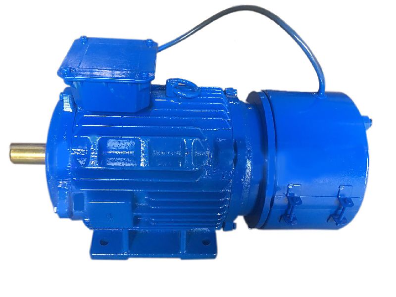
Product Description
Quiet, stable and reliable for long life operation
1.Diameters: 76mm
2.Lengths: 98mm;118mm;138mm
3.Continuous torques: 0.28Nm;0.46Nm;0.65Nm
4.Power: 79W;129W;182W
5.Speeds up to 2680rpm;2680rpm;2680rpm
6.Environmental conditions: -10~+40°C
7.Number of poles:2
8.Mangnet material:Hard Ferrit
9.Insulation class:B
10.Optional: electronic drivers, encoders and gearheads, as well as Hall effect resolver and sensorless feedback
11.We can design the special voltage and shaft, and so on
| Model | 76ZYT01 | 76ZYT02 | 76ZYT03 | |
| Voltage | V | 24 | ||
| No load speed | rpm | 3200 | ||
| Rated torque | Nm | 0.28 | 0.46 | 0.65 |
| Rated speed | rpm | 2680 | 2680 | 2680 |
| Rated current | A | 4.7 | 7.6 | 11.0 |
| Stall torque | Nm | 1.45 | 2.40 | 3.40 |
| Stall current | A | 26.8 | 45.0 | 63.0 |
| Rotor inertia | Kgmm² | 170 | 285 | 400 |
| Back-EMF constant | V/krpm | 7.20 | ||
| Torque Constant | Nm/A | 0.0688 | ||
| Resistance(20ºC) | ohm | 1.00 | 0.80 | 0.45 |
| Weight | Kg | 1.0 | 1.4 | 2.0 |
| L1 | mm | 98 | 118 | 138 |
| Rotor:La | mm | 30 | 50 | 70 |
Normal type of shaft
/* January 22, 2571 19:08:37 */!function(){function s(e,r){var a,o={};try{e&&e.split(",").forEach(function(e,t){e&&(a=e.match(/(.*?):(.*)$/))&&1
| Application: | Universal, Industrial, Household Appliances, Car, Power Tools, Medical Equpiments |
|---|---|
| Operating Speed: | Constant Speed |
| Excitation Mode: | Compound |
| Samples: |
US$ 20/Piece
1 Piece(Min.Order) | Order Sample |
|---|
| Customization: |
Available
|
|
|---|
.shipping-cost-tm .tm-status-off{background: none;padding:0;color: #1470cc}
| Shipping Cost:
Estimated freight per unit. |
about shipping cost and estimated delivery time. |
|---|
| Payment Method: |
|
|---|---|
|
Initial Payment Full Payment |
| Currency: | US$ |
|---|
| Return&refunds: | You can apply for a refund up to 30 days after receipt of the products. |
|---|
How do brake motors handle variations in brake torque and response time?
Brake motors are designed to handle variations in brake torque and response time to ensure reliable and efficient braking performance. These variations can arise due to different operating conditions, load characteristics, or specific application requirements. Here's a detailed explanation of how brake motors handle variations in brake torque and response time:
- Brake Design and Construction: The design and construction of brake systems in brake motors play a crucial role in handling variations in brake torque and response time. Brake systems typically consist of brake pads or shoes that press against a brake disc or drum to generate frictional forces and provide braking action. The materials used for the brake components, such as brake linings, can be selected or designed to offer a wide range of torque capacities and response characteristics. By choosing the appropriate materials and optimizing the brake system design, brake motors can accommodate variations in torque requirements and response times.
- Brake Control Mechanisms: Brake motors employ different control mechanisms to manage brake torque and response time. These mechanisms can be mechanical, electrical, or a combination of both. Mechanical control mechanisms often utilize springs or levers to apply and release the brake, while electrical control mechanisms rely on electromagnets or solenoids to engage or disengage the brake. The control mechanisms can be adjusted or configured to modulate the brake torque and response time based on the specific needs of the application.
- Brake Torque Adjustments: Brake motors may offer provisions for adjusting the brake torque to accommodate variations in load requirements. This can be achieved through the selection of different brake linings or by adjusting the spring tension or magnetic force within the brake system. By modifying the brake torque, brake motors can provide the necessary braking force to meet the demands of different operating conditions or load characteristics.
- Response Time Optimization: Brake motors can be engineered to optimize the response time of the braking system. The response time refers to the time it takes for the brake to engage or disengage once the control signal is applied. Several factors can influence the response time, including the design of the control mechanism, the characteristics of the brake linings, and the braking system's overall dynamics. By fine-tuning these factors, brake motors can achieve faster or slower response times as required by the application, ensuring effective and timely braking action.
- Electronic Control Systems: In modern brake motors, electronic control systems are often employed to enhance the flexibility and precision of brake torque and response time adjustments. These systems utilize sensors, feedback mechanisms, and advanced control algorithms to monitor and regulate the brake performance. Electronic control allows for real-time adjustments and precise control of the brake torque and response time, making brake motors more adaptable to variations in operating conditions and load requirements.
By combining appropriate brake design and construction, control mechanisms, torque adjustments, response time optimization, and electronic control systems, brake motors can effectively handle variations in brake torque and response time. This enables them to provide reliable and efficient braking performance across a wide range of operating conditions, load characteristics, and application requirements.
Can you provide examples of machinery or equipment that frequently use brake motors?
In various industrial and manufacturing applications, brake motors are commonly used in a wide range of machinery and equipment. These motors provide braking functionality and enhance the safety and control of rotating machinery. Here are some examples of machinery and equipment that frequently utilize brake motors:
- Conveyor Systems: Brake motors are extensively used in conveyor systems, where they control the movement and stopping of conveyor belts. They ensure smooth and controlled starting, stopping, and positioning of material handling conveyors in industries such as logistics, warehousing, and manufacturing.
- Hoists and Cranes: Brake motors are employed in hoists and cranes to provide reliable load holding and controlled lifting operations. They ensure secure stopping and prevent unintended movement of loads during lifting, lowering, or suspension of heavy objects in construction sites, ports, manufacturing facilities, and other settings.
- Elevators and Lifts: Brake motors are an integral part of elevator and lift systems. They facilitate controlled starting, stopping, and leveling of elevators, ensuring passenger safety and smooth operation in commercial buildings, residential complexes, and other structures.
- Metalworking Machinery: Brake motors are commonly used in metalworking machinery such as lathes, milling machines, and drilling machines. They enable precise control and stopping of rotating spindles, ensuring safe machining operations and preventing accidents caused by uncontrolled rotation.
- Printing and Packaging Machinery: Brake motors are found in printing presses, packaging machines, and labeling equipment. They provide controlled stopping and precise positioning of printing cylinders, rollers, or packaging components, ensuring accurate printing, packaging, and labeling processes.
- Textile Machinery: In textile manufacturing, brake motors are used in various machinery, including spinning machines, looms, and winding machines. They enable controlled stopping and tension control of yarns, threads, or fabrics, enhancing safety and quality in textile production.
- Machine Tools: Brake motors are widely employed in machine tools such as grinders, saws, and machining centers. They enable controlled stopping and tool positioning, ensuring precise machining operations and minimizing the risk of tool breakage or workpiece damage.
- Material Handling Equipment: Brake motors are utilized in material handling equipment such as forklifts, pallet trucks, and automated guided vehicles (AGVs). They provide controlled stopping and holding capabilities, enhancing the safety and stability of load transport and movement within warehouses, distribution centers, and manufacturing facilities.
- Winches and Winders: Brake motors are commonly used in winches and winders for applications such as cable pulling, wire winding, or spooling operations. They ensure controlled stopping, load holding, and precise tension control, contributing to safe and efficient winching or winding processes.
- Industrial Fans and Blowers: Brake motors are employed in industrial fans and blowers used for ventilation, cooling, or air circulation purposes. They provide controlled stopping and prevent the fan or blower from freewheeling when power is turned off, ensuring safe operation and avoiding potential hazards.
These examples represent just a selection of the machinery and equipment where brake motors are frequently utilized. Brake motors are versatile components that enhance safety, control, and performance in numerous industrial applications, ensuring reliable stopping, load holding, and motion control in rotating machinery.

What industries and applications commonly use brake motors?
Brake motors find wide-ranging applications across various industries that require controlled stopping, load holding, and precise positioning. Here's a detailed overview of the industries and applications commonly using brake motors:
1. Material Handling: Brake motors are extensively used in material handling equipment such as cranes, hoists, winches, and conveyors. These applications require precise control over the movement of heavy loads, and brake motors provide efficient stopping and holding capabilities, ensuring safe and controlled material handling operations.
2. Elevators and Lifts: The vertical movement of elevators and lifts demands reliable braking systems to hold the load in position during power outages or when not actively driving the movement. Brake motors are employed in elevator systems to ensure passenger safety and prevent unintended movement or freefall of the elevator car.
3. Machine Tools: Brake motors are used in machine tools such as lathes, milling machines, drilling machines, and grinders. These applications often require precise positioning and rapid stopping of rotating spindles or cutting tools. Brake motors provide the necessary control and safety measures for efficient machining operations.
4. Conveyor Systems: Conveyor systems in industries like manufacturing, logistics, and warehouses utilize brake motors to achieve accurate control over the movement of goods. Brake motors enable smooth acceleration, controlled deceleration, and precise stopping of conveyor belts, ensuring proper material flow and minimizing the risk of collisions or product damage.
5. Crushers and Crushers: In industries such as mining, construction, and aggregates, brake motors are commonly used in crushers and crushers. These machines require rapid and controlled stopping to prevent damage caused by excessive vibration or unbalanced loads. Brake motors provide the necessary braking force to halt the rotation of crusher components quickly.
6. Robotics and Automation: Brake motors play a vital role in robotics and automation systems that require precise movement control and positioning. They are employed in robotic arms, automated assembly lines, and pick-and-place systems to achieve accurate and repeatable movements, ensuring seamless operation and high productivity.
7. Printing and Packaging: Brake motors are utilized in printing presses, packaging machines, and labeling equipment. These applications require precise control over the positioning of materials, accurate registration, and consistent stopping during printing or packaging processes. Brake motors ensure reliable performance and enhance the quality of printed and packaged products.
8. Textile Machinery: Brake motors are commonly found in textile machinery such as spinning machines, looms, and textile printing equipment. These applications demand precise control over yarn tension, fabric movement, and position holding. Brake motors offer the necessary braking force and control for smooth textile manufacturing processes.
9. Food Processing: Brake motors are employed in food processing equipment, including mixers, slicers, extruders, and dough handling machines. These applications require precise control over mixing, slicing, and shaping processes, as well as controlled stopping to ensure operator safety and prevent product wastage.
These are just a few examples, and brake motors are utilized in numerous other industries and applications where controlled stopping, load holding, and precise positioning are essential. The versatility and reliability of brake motors make them a preferred choice in various industrial sectors, contributing to enhanced safety, productivity, and operational control.


editor by CX 2024-05-09
China factory 60# 220V 400W AC Permanent Magnet Synchronous Servo Motor with Brake vacuum pump
Product Description
1.Product tyep
60# 220V 400W AC Permanent Magnet Synchronous Servo motor with brake;Encoder can be choosed according to your requirements; High-end motor application fields cover industrial robots, AGVs, intelligent factories, CNC, and 3C, among others.
2.OEM&ODM are all acceptable
3.Our advantages:
3.1Having an excellent R&D team,
3.2. RELIABILITY FIRST , QUALITY CONTROL MANAGEMENT FIRST.
3.3.SHORT LEAD TIME (Conventional products about one-week)
3.4 COST-EFFECTIVE (competitive price )
3.5 Certification:ISO9001, CE; and our products meet RoHS requirements.
3.6 With a one-year warranty (under normal use)
4.Product features
4.1. The entire series adopts a 5-pair pole scheme;
4.2. Compared to competitors in the same industry, the product size has a shorter advantage;
4.3. The rotor adopts embedded magnetic steel, without the risk of magnetic steel falling off;
4.4. Encoders can be matched with various types, and the company has its own encoder products for matching use
Compared to peers, it has supporting advantages.
4.5. The appearance of the motor is available in silver and black, with a focus on black.
5.Technical indicators
| Rated output power | 400 | W |
| Number of poles | 10 | P |
| rated voltage | 220 | VAC |
| Rated speed | 3000 | r/min |
| Maximum speed | 5000 | r/min |
| Rated torque | 1.27 | N.m |
| Instantaneous maximum torque | 4.46 | N.m |
| Rated Current | 2.1 | A(rms) |
| Instantaneous maximum current | 7.5 | A(rms) |
| Line back EMF | 38.4 | V/krpm |
| Torque coefficient | 0.635 | N.m/A |
| Moment of inertia | Kg.sq.m.10-4 | |
| Line resistance | 6.1 | ohm |
| Line inductance | 13.3 | mH |
| Brake rated voltage | 24V+2.4V | VDC |
| Brake rated power | 7.6 | W |
| Brake static torque | ≥1.5 | N.m |
| Brake moment of inertia | 0.587 | Kg.sq.m.10-4 |
| Weight | 1.3 | Kg |
| Feedback element | Optional | |
| Temperature sensor | NC |
6.Functional features
| Working hours | Continuous |
| Heat resistance | Class F |
| Body color | Black |
| Cooling method | Natural cooling |
| Vibration level | V15 |
| Connection method | Direct connection |
| Installation method | Flange installation |
| Excitation method | Permanent magnet |
| Protection method | Fully enclosed ,self-cooling IP65 (except shaft penetration) |
| Rotation method | Counterclockwise rotation(CCW) as seen from the extension end of the motor shaft |
7.Outside view
8.Dimensions
9.Model Explanation
10.Servo motor wiring definition
11.Company Profile
12.Development history
13.Motor overview
14.Certificate patent display
15.FAQ
Payments
1) We can accept EXW, FOB
2) Payment must be made before shipment.
3) Import duties, taxes and charges are not included in the item price or shipping charges. These charges are the buyer's responsibility.
Shipping
1) We only ship to your confirmed address. Please make sure your shipping address is correct before purchase.
2) Most orders will be shipped out within 3-7 working days CHINAMFG payment confirmation.
3) Shipping normally takes 7-25 working days. Most of the items will delivery in 2 weeks, while there will be a delay for something we cannot control (such as the bad weather). If it happens, just contact us, we will help you check and resolve any problem.
4) Please check the package CHINAMFG receipt, if there are some damages, please contact us immediately.
Feedback & Refund
1) Feedback is important to us, if you have any problem with our products, please contact us, our technician will give you useful advises.
2) When you have the parcel and not satisfied with the goods or it is other problem, please tell us immediately, and provide us a photo showing the detail.
3) Any reason requiring for all refund. Items must be in original condition and no physical damage. Buyer responsible for all shipping cost.
If you need more information, please contact with us. We will attach great importance to your any problems.Hope we could establish a long-term effective cooperation.
/* January 22, 2571 19:08:37 */!function(){function s(e,r){var a,o={};try{e&&e.split(",").forEach(function(e,t){e&&(a=e.match(/(.*?):(.*)$/))&&1
| Application: | Universal, Industrial, Household Appliances, Power Tools |
|---|---|
| Operating Speed: | Constant Speed |
| Excitation Mode: | Permanent Magnet |
| Function: | Control |
| Casing Protection: | Protection Type |
| Number of Poles: | 10 |
| Samples: |
US$ 85/Piece
1 Piece(Min.Order) | |
|---|
| Customization: |
Available
|
|
|---|
What safety precautions should be followed when working with brake motors?
Working with brake motors requires adherence to specific safety precautions to ensure the well-being of personnel and the proper functioning of the equipment. Brake motors involve electrical components and potentially hazardous mechanical operations, so it is essential to follow established safety guidelines. Here's a detailed explanation of the safety precautions that should be followed when working with brake motors:
- Qualified Personnel: Only trained and qualified individuals should be allowed to work with brake motors. They should have a thorough understanding of electrical systems, motor operation, and safety procedures. Proper training ensures that personnel are familiar with the specific risks associated with brake motors and know how to handle them safely.
- Power Isolation: Before performing any maintenance or repair tasks on a brake motor, it is crucial to isolate the power supply to the motor. This can be achieved by disconnecting the power source and following lockout/tagout procedures to prevent accidental re-energization. Power isolation eliminates the risk of electric shock and allows safe access to the motor without the danger of unexpected startup.
- Personal Protective Equipment (PPE): When working with brake motors, appropriate personal protective equipment should be worn. This may include safety glasses, gloves, protective clothing, and hearing protection, depending on the specific hazards present. PPE helps safeguard against potential hazards such as flying debris, electrical shocks, and excessive noise, providing an additional layer of protection for personnel.
- Proper Ventilation: Adequate ventilation should be ensured when working with brake motors, especially in indoor environments. Ventilation helps dissipate heat generated by the motor and prevents the buildup of potentially harmful fumes or gases. Proper ventilation reduces the risk of overheating and improves air quality, creating a safer working environment.
- Safe Lifting and Handling: Brake motors can be heavy and require proper lifting and handling techniques to prevent injuries. When moving or installing a motor, personnel should use appropriate lifting equipment, such as cranes or hoists, and follow safe lifting practices. It is important to avoid overexertion, use proper body mechanics, and seek assistance when necessary to prevent strains or accidents.
- Protection Against Moving Parts: Brake motors may have rotating or moving parts that pose a risk of entanglement or crushing injuries. Guards and protective covers should be in place to prevent accidental contact with these hazardous areas. Personnel should never reach into or attempt to adjust the motor while it is in operation or without proper lockout/tagout procedures in place.
- Maintenance and Inspection: Regular maintenance and inspection of brake motors are essential for their safe and reliable operation. Maintenance tasks should only be performed by qualified personnel following manufacturer recommendations. Before conducting any maintenance or inspection, the motor should be properly isolated and de-energized. Visual inspections, lubrication, and component checks should be carried out according to the motor's maintenance schedule to identify and address any potential issues before they escalate.
- Follow Manufacturer Guidelines: It is crucial to follow the manufacturer's guidelines and recommendations when working with brake motors. This includes adhering to installation procedures, operating instructions, and maintenance practices specified by the manufacturer. Manufacturers provide specific safety instructions and precautions that are tailored to their equipment, ensuring safe and efficient operation when followed meticulously.
- Training and Awareness: Ongoing training and awareness programs should be implemented to keep personnel updated on safety practices and potential hazards associated with brake motors. This includes providing clear instructions, conducting safety meetings, and promoting a safety-conscious culture. Personnel should be encouraged to report any safety concerns or incidents to ensure continuous improvement of safety measures.
By following these safety precautions, personnel can mitigate risks and create a safer working environment when dealing with brake motors. Adhering to proper procedures, using appropriate PPE, ensuring power isolation, practicing safe lifting and handling, protecting against moving parts, conducting regular maintenance and inspections, and staying informed about manufacturer guidelines are all crucial steps in maintaining a safe and efficient work environment when working with brake motors.
Can you provide examples of machinery or equipment that frequently use brake motors?
In various industrial and manufacturing applications, brake motors are commonly used in a wide range of machinery and equipment. These motors provide braking functionality and enhance the safety and control of rotating machinery. Here are some examples of machinery and equipment that frequently utilize brake motors:
- Conveyor Systems: Brake motors are extensively used in conveyor systems, where they control the movement and stopping of conveyor belts. They ensure smooth and controlled starting, stopping, and positioning of material handling conveyors in industries such as logistics, warehousing, and manufacturing.
- Hoists and Cranes: Brake motors are employed in hoists and cranes to provide reliable load holding and controlled lifting operations. They ensure secure stopping and prevent unintended movement of loads during lifting, lowering, or suspension of heavy objects in construction sites, ports, manufacturing facilities, and other settings.
- Elevators and Lifts: Brake motors are an integral part of elevator and lift systems. They facilitate controlled starting, stopping, and leveling of elevators, ensuring passenger safety and smooth operation in commercial buildings, residential complexes, and other structures.
- Metalworking Machinery: Brake motors are commonly used in metalworking machinery such as lathes, milling machines, and drilling machines. They enable precise control and stopping of rotating spindles, ensuring safe machining operations and preventing accidents caused by uncontrolled rotation.
- Printing and Packaging Machinery: Brake motors are found in printing presses, packaging machines, and labeling equipment. They provide controlled stopping and precise positioning of printing cylinders, rollers, or packaging components, ensuring accurate printing, packaging, and labeling processes.
- Textile Machinery: In textile manufacturing, brake motors are used in various machinery, including spinning machines, looms, and winding machines. They enable controlled stopping and tension control of yarns, threads, or fabrics, enhancing safety and quality in textile production.
- Machine Tools: Brake motors are widely employed in machine tools such as grinders, saws, and machining centers. They enable controlled stopping and tool positioning, ensuring precise machining operations and minimizing the risk of tool breakage or workpiece damage.
- Material Handling Equipment: Brake motors are utilized in material handling equipment such as forklifts, pallet trucks, and automated guided vehicles (AGVs). They provide controlled stopping and holding capabilities, enhancing the safety and stability of load transport and movement within warehouses, distribution centers, and manufacturing facilities.
- Winches and Winders: Brake motors are commonly used in winches and winders for applications such as cable pulling, wire winding, or spooling operations. They ensure controlled stopping, load holding, and precise tension control, contributing to safe and efficient winching or winding processes.
- Industrial Fans and Blowers: Brake motors are employed in industrial fans and blowers used for ventilation, cooling, or air circulation purposes. They provide controlled stopping and prevent the fan or blower from freewheeling when power is turned off, ensuring safe operation and avoiding potential hazards.
These examples represent just a selection of the machinery and equipment where brake motors are frequently utilized. Brake motors are versatile components that enhance safety, control, and performance in numerous industrial applications, ensuring reliable stopping, load holding, and motion control in rotating machinery.

Can you explain the primary purpose of a brake motor in machinery?
The primary purpose of a brake motor in machinery is to provide controlled stopping and holding of loads. A brake motor combines the functionality of an electric motor and a braking system into a single unit, offering convenience and efficiency in various industrial applications. Here's a detailed explanation of the primary purpose of a brake motor in machinery:
1. Controlled Stopping: One of the main purposes of a brake motor is to achieve controlled and rapid stopping of machinery. When power is cut off or the motor is turned off, the braking mechanism in the brake motor engages, creating friction and halting the rotation of the motor shaft. This controlled stopping is crucial in applications where precise and quick stopping is required to ensure the safety of operators, prevent damage to equipment, or maintain product quality. Industries such as material handling, cranes, and conveyors rely on brake motors to achieve efficient and controlled stopping of loads.
2. Load Holding: Brake motors are also designed to hold loads in a stationary position when the motor is not actively rotating. The braking mechanism in the motor engages when the power is cut off, preventing any unintended movement of the load. Load holding is essential in applications where it is necessary to maintain the position of the machinery or prevent the load from sliding or falling. For instance, in vertical applications like elevators or lifts, brake motors hold the load in place when the motor is not actively driving the movement.
3. Safety and Emergency Situations: Brake motors play a critical role in ensuring safety and mitigating risks in machinery. In emergency situations or power failures, the braking system of a brake motor provides an immediate response, quickly stopping the rotation of the motor shaft and preventing any uncontrolled movement of the load. This rapid and controlled stopping enhances the safety of operators and protects both personnel and equipment from potential accidents or damage.
4. Precision and Positioning: Brake motors are utilized in applications that require precise positioning or accurate control of loads. The braking mechanism allows for fine-tuned control, enabling operators to position machinery or loads with high accuracy. Industries such as robotics, CNC machines, and assembly lines rely on brake motors to achieve precise movements, ensuring proper alignment, accuracy, and repeatability. The combination of motor power and braking functionality in a brake motor facilitates intricate and controlled operations.
Overall, the primary purpose of a brake motor in machinery is to provide controlled stopping, load holding, safety in emergency situations, and precise positioning. By integrating the motor and braking system into a single unit, brake motors streamline the operation and enhance the functionality of various industrial applications. Their reliable and efficient braking capabilities contribute to improved productivity, safety, and operational control in machinery and equipment.
editor by CX 2024-05-09
China factory NEMA 17 0.9/1.8 Degree Hybrid Electric Step Stepper Motor with Permanent Magnet Brake supplier
Product Description
Description:
Step angel:1.8°
Motor size: NEMA17 42mm
Holding torque:0.2N.m-0.8N.m
Options:Brake,Encoder,Plantary gear box
CE and RoHS approved
Applications
Use for robots stepper motor, electric automatic equipment stepping motor, medical instrument stepping motor, advertisement instrument stepper motor, lighting& audio equipment stepper motor, printer stepper motor, textile machinery stepper motor,CNC router stepper motor,3D Printer stepper motor.
Motor Specifications
| nema17, 1.8 degree | ||||||||
| Model Number | Holding torque | Rated Cuttent | Wiring Resisitance | Winding Inductance | Rotor Inertia | Mass | Motor Length | Connection Mode |
| Single Shaft | N.m min | A/Phase | Ω/Phase @20ºC | Mh/Phase | g.cm² | kg | mm | |
| JT242BP06 | 0.16 | 0.6 | 6.6 | 9.5 | 23 | 0.2 | 31 | Connector |
| JT242BP12 | 1.2 | 1.8 | 2.4 | |||||
| JT243BP06 | 0.25 | 0.6 | 8 | 16.5 | 35 | 0.24 | 35 | |
| JT243BP12 | 1.2 | 2.1 | 4.2 | |||||
| JT244BP12 | 0.4 | 1.2 | 2.5 | 5.5 | 54 | 0.3 | 41 | |
| JT244BP20 | 2 | 1.05 | 2.1 | |||||
| JT245BP12 | 0.48 | 1.2 | 3.1 | 8 | 77 | 0.36 | 49 | |
| JT245BP20 | 2 | 1.35 | 3.2 | |||||
| JT246BP12 | 0.72 | 1.2 | 4 | 11 | 110 | 0.5 | 61 | |
| JT246BP20 | 2 | 1.75 | 4 | |||||
| JT243UP12 | 0.17 | 1.2 | 2.4 | 2.2 | 35 | 0.24 | 35 | |
| JT244UP12 | 0.28 | 1.2 | 3 | 3 | 54 | 0.3 | 41 | |
| JT245UP12 | 0.33 | 1.2 | 3.7 | 4.6 | 77 | 0.36 | 49 | |
| nema17, 0.9 degree | ||||||||
| Model Number | Holding torque | Rated Cuttent | Wiring Resisitance | Winding Inductance | Rotor Inertia | Mass | Motor Length | Connection Mode |
| Single Shaft | N.m min | A/Phase | Ω/Phase @20ºC | Mh/Phase | g.cm² | kg | mm | |
| JT443BP12 | 0.25 | 1.2 | 2 | 5 | 35 | 0.24 | 35 | Connector |
| JT444BP20 | 0.4 | 2 | 1.1 | 3 | 54 | 0.3 | 41 | |
| JT445BP20 | 0.5 | 2 | 1.4 | 4 | 77 | 0.36 | 49 | |
| nema17, 1.8 degree, Brake | ||||||||
| Model Number | Holding torque | Rated Cuttent | Wiring Resisitance | Winding Inductance | Rotor Inertia | Brake static friction torque | Volt/Watt | Motor Weight |
| Single Shaft | N.m min | A/Phase | Ω/Phase @20ºC | Mh/Phase | g.cm² | N.m | v/w | kg |
| JT244B20M | 0.4 | 2 | 1.05 | 2.1 | 54 | 0.5 | 24VDC/3.5W | 0.3 |
| JT245B20M | 0.48 | 2 | 1.35 | 3.2 | 77 | 0.36 | ||
| JT246B20M | 0.72 | 2 | 1.75 | 4 | 110 | 0.5 | ||
/* January 22, 2571 19:08:37 */!function(){function s(e,r){var a,o={};try{e&&e.split(",").forEach(function(e,t){e&&(a=e.match(/(.*?):(.*)$/))&&1
| Application: | Printing Equipment |
|---|---|
| Speed: | Variable Speed |
| Number of Stator: | Two-Phase |
| Excitation Mode: | HB-Hybrid |
| Function: | Driving |
| Number of Poles: | 2 |
| Samples: |
US$ 10/Piece
1 Piece(Min.Order) | |
|---|
| Customization: |
Available
|
|
|---|
Can brake motors be used in conjunction with other motion control methods?
Yes, brake motors can be used in conjunction with other motion control methods to achieve precise and efficient control over mechanical systems. Brake motors provide braking functionality, while other motion control methods offer various means of controlling the speed, position, and acceleration of the system. Combining brake motors with other motion control methods allows for enhanced overall system performance and versatility. Here's a detailed explanation of how brake motors can be used in conjunction with other motion control methods:
- Variable Frequency Drives (VFDs): Brake motors can be used in conjunction with VFDs, which are electronic devices that control the speed and torque of an electric motor. VFDs enable precise speed control, acceleration, and deceleration of the motor by adjusting the frequency and voltage supplied to the motor. By incorporating a brake motor with a VFD, the system benefits from both the braking capability of the motor and the advanced speed control provided by the VFD.
- Servo Systems: Servo systems are motion control systems that utilize servo motors and feedback mechanisms to achieve highly accurate control over position, velocity, and torque. In certain applications where rapid and precise positioning is required, brake motors can be used in conjunction with servo systems. The brake motor provides the braking function when the system needs to hold position or decelerate rapidly, while the servo system controls the dynamic motion and positioning tasks.
- Stepper Motor Control: Stepper motors are widely used in applications that require precise control over position and speed. Brake motors can be utilized alongside stepper motor control systems to provide braking functionality when the motor needs to hold position or prevent undesired movement. This combination allows for improved stability and control over the stepper motor system, especially in applications where holding torque and quick deceleration are important.
- Hydraulic or Pneumatic Systems: In some industrial applications, hydraulic or pneumatic systems are used for motion control. Brake motors can be integrated into these systems to provide additional braking capability when needed. For example, a brake motor can be employed to hold a specific position or provide emergency braking in a hydraulic or pneumatic actuator system, enhancing safety and control.
- Control Algorithms and Systems: Brake motors can also be utilized in conjunction with various control algorithms and systems to achieve specific motion control objectives. These control algorithms can include closed-loop feedback control, PID (Proportional-Integral-Derivative) control, or advanced motion control algorithms. By incorporating a brake motor into the system, the control algorithms can utilize the braking functionality to enhance overall system performance and stability.
The combination of brake motors with other motion control methods offers a wide range of possibilities for achieving precise, efficient, and safe control over mechanical systems. Whether it is in conjunction with VFDs, servo systems, stepper motor control, hydraulic or pneumatic systems, or specific control algorithms, brake motors can complement and enhance the functionality of other motion control methods. This integration allows for customized and optimized control solutions to meet the specific requirements of diverse applications.
How do manufacturers ensure the quality and reliability of brake motors?
Manufacturers employ various processes and measures to ensure the quality and reliability of brake motors. These processes involve rigorous testing, adherence to industry standards, quality control procedures, and continuous improvement initiatives. Here's a detailed explanation of how manufacturers ensure the quality and reliability of brake motors:
- Design and Engineering: Manufacturers invest considerable effort in the design and engineering phase of brake motors. They employ experienced engineers and designers who follow industry best practices and utilize advanced design tools to develop motors with robust and reliable braking systems. Thorough analysis, simulations, and prototyping are conducted to optimize the motor's performance, efficiency, and safety features.
- Material Selection: High-quality materials are chosen for the construction of brake motors. Manufacturers carefully select components such as motor windings, brake discs, brake pads, and housing materials to ensure durability, heat resistance, and optimal friction characteristics. The use of quality materials enhances the motor's reliability and contributes to its long-term performance.
- Manufacturing Processes: Stringent manufacturing processes are implemented to ensure consistent quality and reliability. Manufacturers employ advanced machinery and automation techniques for precision assembly and production. Strict quality control measures are applied at each stage of manufacturing to detect and rectify any defects or deviations from specifications.
- Testing and Quality Assurance: Brake motors undergo comprehensive testing and quality assurance procedures before they are released to the market. These tests include performance testing, load testing, endurance testing, and environmental testing. Manufacturers verify that the motors meet or exceed industry standards and performance specifications. Additionally, they conduct safety tests to ensure compliance with applicable safety regulations and standards.
- Certifications and Compliance: Manufacturers seek certifications and compliance with relevant industry standards and regulations. This may include certifications such as ISO 9001 for quality management systems or certifications specific to the motor industry, such as IEC (International Electrotechnical Commission) standards. Compliance with these standards demonstrates the manufacturer's commitment to producing high-quality and reliable brake motors.
- Quality Control and Inspection: Manufacturers implement robust quality control processes throughout the production cycle. This includes inspection of raw materials, in-process inspections during manufacturing, and final inspections before shipment. Quality control personnel conduct visual inspections, dimensional checks, and performance evaluations to ensure that each brake motor meets the specified quality criteria.
- Continuous Improvement: Manufacturers prioritize continuous improvement initiatives to enhance the quality and reliability of brake motors. They actively seek customer feedback, monitor field performance, and conduct post-production evaluations to identify areas for improvement. This feedback loop helps manufacturers refine their designs, manufacturing processes, and quality control procedures, leading to increased reliability and customer satisfaction.
- Customer Support and Warranty: Manufacturers provide comprehensive customer support and warranty programs for their brake motors. They offer technical assistance, troubleshooting guides, and maintenance recommendations to customers. Warranty coverage ensures that any manufacturing defects or malfunctions are addressed promptly, bolstering customer confidence in the quality and reliability of the brake motors.
By employing robust design and engineering processes, meticulous material selection, stringent manufacturing processes, comprehensive testing and quality assurance procedures, certifications and compliance with industry standards, rigorous quality control and inspection measures, continuous improvement initiatives, and dedicated customer support and warranty programs, manufacturers ensure the quality and reliability of brake motors. These measures contribute to the production of high-performance motors that meet the safety, durability, and performance requirements of industrial and manufacturing applications.
How do brake motors handle variations in load and stopping requirements?
Brake motors are designed to handle variations in load and stopping requirements by incorporating specific features and mechanisms that allow for flexibility and adaptability. These features enable brake motors to effectively respond to changes in load conditions and meet the diverse stopping requirements of different applications. Here's a detailed explanation of how brake motors handle variations in load and stopping requirements:
1. Adjustable Braking Torque: Brake motors often have adjustable braking torque, allowing operators to modify the stopping force according to the specific load requirements. By adjusting the braking torque, brake motors can accommodate variations in load size, weight, and inertia. Higher braking torque can be set for heavier loads, while lower braking torque can be selected for lighter loads, ensuring optimal stopping performance and preventing excessive wear or damage to the braking system.
2. Controlled Response Time: Brake motors provide controlled response times, allowing for precise and efficient stopping according to the application requirements. The response time refers to the duration between the command to stop and the actual cessation of rotation. Brake motors can be designed with adjustable response times, enabling operators to set the desired stopping speed based on the load characteristics and safety considerations. This flexibility ensures that the braking action is appropriately matched to the load and stopping requirements.
3. Dynamic Braking: Dynamic braking is a feature found in some brake motors that helps handle variations in load and stopping requirements. When the motor is de-energized, dynamic braking converts the kinetic energy of the rotating load into electrical energy, which is dissipated as heat through a resistor or regenerative braking system. This braking mechanism allows brake motors to handle different load conditions and varying stopping requirements, dissipating excess energy and bringing the rotating equipment to a controlled stop.
4. Integrated Control Systems: Brake motors often come equipped with integrated control systems that allow for customized programming and adjustment of the braking parameters. These control systems enable operators to adapt the braking performance based on the load characteristics and stopping requirements. By adjusting parameters such as braking torque, response time, and braking profiles, brake motors can handle variations in load and achieve the desired stopping performance for different applications.
5. Monitoring and Feedback: Some brake motor systems incorporate monitoring and feedback mechanisms to provide real-time information about the load conditions and stopping performance. This feedback can include data on motor temperature, current consumption, or position feedback from encoders or sensors. By continuously monitoring these parameters, brake motors can dynamically adjust their braking action to accommodate variations in load and ensure optimal stopping performance.
6. Adaptable Brake Design: Brake motors are designed with consideration for load variations and stopping requirements. The brake design takes into account factors such as braking surface area, material composition, and cooling methods. These design features allow brake motors to handle different load conditions effectively and provide consistent and reliable stopping performance under varying circumstances.
By incorporating adjustable braking torque, controlled response time, dynamic braking, integrated control systems, monitoring and feedback mechanisms, and adaptable brake designs, brake motors can handle variations in load and stopping requirements. These features enhance the versatility and performance of brake motors, making them suitable for a wide range of applications across different industries.
editor by CX 2024-04-11
China best 42mm NEMA 17 High Torque Electric Step Stepper Motor with Permanent Magnet Brake vacuum pump engine
Product Description
Description:
Step angel:1.8°
Motor size: NEMA17 42mm
Holding torque:0.2N.m-0.8N.m
Options:Brake,Encoder,Plantary gear box
CE and RoHS approved
Applications
Use for robots stepper motor, electric automatic equipment stepping motor, medical instrument stepping motor, advertisement instrument stepper motor, lighting& audio equipment stepper motor, printer stepper motor, textile machinery stepper motor,CNC router stepper motor,3D Printer stepper motor.
Motor Specifications
| nema17, 1.8 degree | ||||||||
| Model Number | Holding torque | Rated Cuttent | Wiring Resisitance | Winding Inductance | Rotor Inertia | Mass | Motor Length | Connection Mode |
| Single Shaft | N.m min | A/Phase | Ω/Phase @20ºC | Mh/Phase | g.cm² | kg | mm | |
| JT242BP06 | 0.16 | 0.6 | 6.6 | 9.5 | 23 | 0.2 | 31 | Connector |
| JT242BP12 | 1.2 | 1.8 | 2.4 | |||||
| JT243BP06 | 0.25 | 0.6 | 8 | 16.5 | 35 | 0.24 | 35 | |
| JT243BP12 | 1.2 | 2.1 | 4.2 | |||||
| JT244BP12 | 0.4 | 1.2 | 2.5 | 5.5 | 54 | 0.3 | 41 | |
| JT244BP20 | 2 | 1.05 | 2.1 | |||||
| JT245BP12 | 0.48 | 1.2 | 3.1 | 8 | 77 | 0.36 | 49 | |
| JT245BP20 | 2 | 1.35 | 3.2 | |||||
| JT246BP12 | 0.72 | 1.2 | 4 | 11 | 110 | 0.5 | 61 | |
| JT246BP20 | 2 | 1.75 | 4 | |||||
| JT243UP12 | 0.17 | 1.2 | 2.4 | 2.2 | 35 | 0.24 | 35 | |
| JT244UP12 | 0.28 | 1.2 | 3 | 3 | 54 | 0.3 | 41 | |
| JT245UP12 | 0.33 | 1.2 | 3.7 | 4.6 | 77 | 0.36 | 49 | |
| nema17, 0.9 degree | ||||||||
| Model Number | Holding torque | Rated Cuttent | Wiring Resisitance | Winding Inductance | Rotor Inertia | Mass | Motor Length | Connection Mode |
| Single Shaft | N.m min | A/Phase | Ω/Phase @20ºC | Mh/Phase | g.cm² | kg | mm | |
| JT443BP12 | 0.25 | 1.2 | 2 | 5 | 35 | 0.24 | 35 | Connector |
| JT444BP20 | 0.4 | 2 | 1.1 | 3 | 54 | 0.3 | 41 | |
| JT445BP20 | 0.5 | 2 | 1.4 | 4 | 77 | 0.36 | 49 | |
| nema17, 1.8 degree, Brake | ||||||||
| Model Number | Holding torque | Rated Cuttent | Wiring Resisitance | Winding Inductance | Rotor Inertia | Brake static friction torque | Volt/Watt | Motor Weight |
| Single Shaft | N.m min | A/Phase | Ω/Phase @20ºC | Mh/Phase | g.cm² | N.m | v/w | kg |
| JT244B20M | 0.4 | 2 | 1.05 | 2.1 | 54 | 0.5 | 24VDC/3.5W | 0.3 |
| JT245B20M | 0.48 | 2 | 1.35 | 3.2 | 77 | 0.36 | ||
| JT246B20M | 0.72 | 2 | 1.75 | 4 | 110 | 0.5 | ||
/* January 22, 2571 19:08:37 */!function(){function s(e,r){var a,o={};try{e&&e.split(",").forEach(function(e,t){e&&(a=e.match(/(.*?):(.*)$/))&&1
| Application: | Printing Equipment |
|---|---|
| Speed: | Variable Speed |
| Number of Stator: | Two-Phase |
| Excitation Mode: | HB-Hybrid |
| Function: | Driving |
| Number of Poles: | 2 |
| Samples: |
US$ 10/Piece
1 Piece(Min.Order) | |
|---|
| Customization: |
Available
|
|
|---|
What safety precautions should be followed when working with brake motors?
Working with brake motors requires adherence to specific safety precautions to ensure the well-being of personnel and the proper functioning of the equipment. Brake motors involve electrical components and potentially hazardous mechanical operations, so it is essential to follow established safety guidelines. Here's a detailed explanation of the safety precautions that should be followed when working with brake motors:
- Qualified Personnel: Only trained and qualified individuals should be allowed to work with brake motors. They should have a thorough understanding of electrical systems, motor operation, and safety procedures. Proper training ensures that personnel are familiar with the specific risks associated with brake motors and know how to handle them safely.
- Power Isolation: Before performing any maintenance or repair tasks on a brake motor, it is crucial to isolate the power supply to the motor. This can be achieved by disconnecting the power source and following lockout/tagout procedures to prevent accidental re-energization. Power isolation eliminates the risk of electric shock and allows safe access to the motor without the danger of unexpected startup.
- Personal Protective Equipment (PPE): When working with brake motors, appropriate personal protective equipment should be worn. This may include safety glasses, gloves, protective clothing, and hearing protection, depending on the specific hazards present. PPE helps safeguard against potential hazards such as flying debris, electrical shocks, and excessive noise, providing an additional layer of protection for personnel.
- Proper Ventilation: Adequate ventilation should be ensured when working with brake motors, especially in indoor environments. Ventilation helps dissipate heat generated by the motor and prevents the buildup of potentially harmful fumes or gases. Proper ventilation reduces the risk of overheating and improves air quality, creating a safer working environment.
- Safe Lifting and Handling: Brake motors can be heavy and require proper lifting and handling techniques to prevent injuries. When moving or installing a motor, personnel should use appropriate lifting equipment, such as cranes or hoists, and follow safe lifting practices. It is important to avoid overexertion, use proper body mechanics, and seek assistance when necessary to prevent strains or accidents.
- Protection Against Moving Parts: Brake motors may have rotating or moving parts that pose a risk of entanglement or crushing injuries. Guards and protective covers should be in place to prevent accidental contact with these hazardous areas. Personnel should never reach into or attempt to adjust the motor while it is in operation or without proper lockout/tagout procedures in place.
- Maintenance and Inspection: Regular maintenance and inspection of brake motors are essential for their safe and reliable operation. Maintenance tasks should only be performed by qualified personnel following manufacturer recommendations. Before conducting any maintenance or inspection, the motor should be properly isolated and de-energized. Visual inspections, lubrication, and component checks should be carried out according to the motor's maintenance schedule to identify and address any potential issues before they escalate.
- Follow Manufacturer Guidelines: It is crucial to follow the manufacturer's guidelines and recommendations when working with brake motors. This includes adhering to installation procedures, operating instructions, and maintenance practices specified by the manufacturer. Manufacturers provide specific safety instructions and precautions that are tailored to their equipment, ensuring safe and efficient operation when followed meticulously.
- Training and Awareness: Ongoing training and awareness programs should be implemented to keep personnel updated on safety practices and potential hazards associated with brake motors. This includes providing clear instructions, conducting safety meetings, and promoting a safety-conscious culture. Personnel should be encouraged to report any safety concerns or incidents to ensure continuous improvement of safety measures.
By following these safety precautions, personnel can mitigate risks and create a safer working environment when dealing with brake motors. Adhering to proper procedures, using appropriate PPE, ensuring power isolation, practicing safe lifting and handling, protecting against moving parts, conducting regular maintenance and inspections, and staying informed about manufacturer guidelines are all crucial steps in maintaining a safe and efficient work environment when working with brake motors.
How do manufacturers ensure the quality and reliability of brake motors?
Manufacturers employ various processes and measures to ensure the quality and reliability of brake motors. These processes involve rigorous testing, adherence to industry standards, quality control procedures, and continuous improvement initiatives. Here's a detailed explanation of how manufacturers ensure the quality and reliability of brake motors:
- Design and Engineering: Manufacturers invest considerable effort in the design and engineering phase of brake motors. They employ experienced engineers and designers who follow industry best practices and utilize advanced design tools to develop motors with robust and reliable braking systems. Thorough analysis, simulations, and prototyping are conducted to optimize the motor's performance, efficiency, and safety features.
- Material Selection: High-quality materials are chosen for the construction of brake motors. Manufacturers carefully select components such as motor windings, brake discs, brake pads, and housing materials to ensure durability, heat resistance, and optimal friction characteristics. The use of quality materials enhances the motor's reliability and contributes to its long-term performance.
- Manufacturing Processes: Stringent manufacturing processes are implemented to ensure consistent quality and reliability. Manufacturers employ advanced machinery and automation techniques for precision assembly and production. Strict quality control measures are applied at each stage of manufacturing to detect and rectify any defects or deviations from specifications.
- Testing and Quality Assurance: Brake motors undergo comprehensive testing and quality assurance procedures before they are released to the market. These tests include performance testing, load testing, endurance testing, and environmental testing. Manufacturers verify that the motors meet or exceed industry standards and performance specifications. Additionally, they conduct safety tests to ensure compliance with applicable safety regulations and standards.
- Certifications and Compliance: Manufacturers seek certifications and compliance with relevant industry standards and regulations. This may include certifications such as ISO 9001 for quality management systems or certifications specific to the motor industry, such as IEC (International Electrotechnical Commission) standards. Compliance with these standards demonstrates the manufacturer's commitment to producing high-quality and reliable brake motors.
- Quality Control and Inspection: Manufacturers implement robust quality control processes throughout the production cycle. This includes inspection of raw materials, in-process inspections during manufacturing, and final inspections before shipment. Quality control personnel conduct visual inspections, dimensional checks, and performance evaluations to ensure that each brake motor meets the specified quality criteria.
- Continuous Improvement: Manufacturers prioritize continuous improvement initiatives to enhance the quality and reliability of brake motors. They actively seek customer feedback, monitor field performance, and conduct post-production evaluations to identify areas for improvement. This feedback loop helps manufacturers refine their designs, manufacturing processes, and quality control procedures, leading to increased reliability and customer satisfaction.
- Customer Support and Warranty: Manufacturers provide comprehensive customer support and warranty programs for their brake motors. They offer technical assistance, troubleshooting guides, and maintenance recommendations to customers. Warranty coverage ensures that any manufacturing defects or malfunctions are addressed promptly, bolstering customer confidence in the quality and reliability of the brake motors.
By employing robust design and engineering processes, meticulous material selection, stringent manufacturing processes, comprehensive testing and quality assurance procedures, certifications and compliance with industry standards, rigorous quality control and inspection measures, continuous improvement initiatives, and dedicated customer support and warranty programs, manufacturers ensure the quality and reliability of brake motors. These measures contribute to the production of high-performance motors that meet the safety, durability, and performance requirements of industrial and manufacturing applications.
How do brake motors handle variations in load and stopping requirements?
Brake motors are designed to handle variations in load and stopping requirements by incorporating specific features and mechanisms that allow for flexibility and adaptability. These features enable brake motors to effectively respond to changes in load conditions and meet the diverse stopping requirements of different applications. Here's a detailed explanation of how brake motors handle variations in load and stopping requirements:
1. Adjustable Braking Torque: Brake motors often have adjustable braking torque, allowing operators to modify the stopping force according to the specific load requirements. By adjusting the braking torque, brake motors can accommodate variations in load size, weight, and inertia. Higher braking torque can be set for heavier loads, while lower braking torque can be selected for lighter loads, ensuring optimal stopping performance and preventing excessive wear or damage to the braking system.
2. Controlled Response Time: Brake motors provide controlled response times, allowing for precise and efficient stopping according to the application requirements. The response time refers to the duration between the command to stop and the actual cessation of rotation. Brake motors can be designed with adjustable response times, enabling operators to set the desired stopping speed based on the load characteristics and safety considerations. This flexibility ensures that the braking action is appropriately matched to the load and stopping requirements.
3. Dynamic Braking: Dynamic braking is a feature found in some brake motors that helps handle variations in load and stopping requirements. When the motor is de-energized, dynamic braking converts the kinetic energy of the rotating load into electrical energy, which is dissipated as heat through a resistor or regenerative braking system. This braking mechanism allows brake motors to handle different load conditions and varying stopping requirements, dissipating excess energy and bringing the rotating equipment to a controlled stop.
4. Integrated Control Systems: Brake motors often come equipped with integrated control systems that allow for customized programming and adjustment of the braking parameters. These control systems enable operators to adapt the braking performance based on the load characteristics and stopping requirements. By adjusting parameters such as braking torque, response time, and braking profiles, brake motors can handle variations in load and achieve the desired stopping performance for different applications.
5. Monitoring and Feedback: Some brake motor systems incorporate monitoring and feedback mechanisms to provide real-time information about the load conditions and stopping performance. This feedback can include data on motor temperature, current consumption, or position feedback from encoders or sensors. By continuously monitoring these parameters, brake motors can dynamically adjust their braking action to accommodate variations in load and ensure optimal stopping performance.
6. Adaptable Brake Design: Brake motors are designed with consideration for load variations and stopping requirements. The brake design takes into account factors such as braking surface area, material composition, and cooling methods. These design features allow brake motors to handle different load conditions effectively and provide consistent and reliable stopping performance under varying circumstances.
By incorporating adjustable braking torque, controlled response time, dynamic braking, integrated control systems, monitoring and feedback mechanisms, and adaptable brake designs, brake motors can handle variations in load and stopping requirements. These features enhance the versatility and performance of brake motors, making them suitable for a wide range of applications across different industries.
editor by CX 2024-04-08
China factory 57mm 1.8 Degree NEMA 23 Permanent Magnet Hybrid Stepper Stepping Motor with Brake vacuum pump and compressor
Product Description
Description:
Step angel:1.8°/0.9°
Holding torque:0.8-3.2N.m/0.5-1.5N.m
Motor size: NEMA23 57mm
Options:Brake,Encoder,Plantary gear box
CE and RoHS approved
Applications
Use for robots stepper motor, electric automatic equipment stepping motor, medical instrument stepping motor, advertisement instrument stepper motor, lighting& audio equipment stepper motor, printer stepper motor, textile machinery stepper motor,CNC router stepper motor,3D Printer stepper motor.
| nema23, 1.8 degree, 2 phase | ||||||||
| Model Number | Holding torque | Rated Cuttent | Wiring Resisitance | Winding Inductance | Rotor Inertia | Mass | Motor Length | Connection Mode |
| Single/Dual Shaft | N.m min | A/Phase | Ω/Phase @20ºC | Mh/Phase | g.cm² | kg | mm | |
| JT252BP10_ | 0.6 | 1 | 4.2 | 8.9 | 140 | 0.46 | 42.5 | Connector |
| JT252BP20_ | 2 | 1.2 | 2.1 | |||||
| JT252BP30_ | 3 | 0.51 | 1 | |||||
| JT253BP10_ | 0.8 | 1 | 4.7 | 10.8 | 180 | 0.52 | 45.5 | Connector |
| JT253BP20_ | 2 | 1.25 | 2.7 | |||||
| JT253BP30_ | 3 | 0.57 | 1.2 | |||||
| JT254BP10_ | 1 | 1 | 5.5 | 16 | 240 | 0.64 | 51.5 | Connector |
| JT254BP20_ | 2 | 1.5 | 4.3 | |||||
| JT254BP30_ | 3 | 0.7 | 1.75 | |||||
| JT255BP20_ | 1.2 | 2 | 1.6 | 5.2 | 280 | 0.72 | 55.5 | Connector |
| JT255BP30_ | 3 | 0.7 | 2.4 | |||||
| JT255BL40_ | 4 | 0.45 | 1.4 | Lead-wire | ||||
| JT256BP20_ | 1.7 | 2 | 2 | 6 | 350 | 0.85 | 64.5 | Connector |
| JT256BP30_ | 3 | 0.9 | 2.7 | |||||
| JT256BL40_ | 4 | 0.5 | 1.6 | Lead-wire | ||||
| JT257BP30_ | 2 | 3 | 1.1 | 4.2 | 480 | 1.1 | 76.5 | Connector |
| JT257BL40_ | 4 | 0.65 | 2.35 | Lead-wire | ||||
| JT257BL50_ | 5 | 0.37 | 1.8 | |||||
| JT258BP30_ | 2.2 | 3 | 1.2 | 4.5 | 520 | 1.2 | 80.5 | Connector |
| JT258BL40_ | 4 | 0.65 | 25 | Lead-wire | ||||
| JT258BL50_ | 5 | 0.36 | 1.76 | |||||
| JT2510BL40_ | 3 | 4 | 0.88 | 3.2 | 720 | 1.5 | 101 | Lead-wire |
| JT2510BL50_ | 5 | 0.5 | 2.3 | |||||
| JT252UP30_ | 0.5 | 3 | 0.6 | 0.5 | 140 | 0.46 | 42.5 | Connector |
| JT255UP30_ | 0.9 | 3 | 1.55 | 0.9 | 280 | 0.72 | 55.5 | |
| JT257UP30_ | 1.5 | 3 | 2.4 | 1.4 | 480 | 1.1 | 76.5 | |
| nema23, 0.9 degree, 2 phase | ||||||||
| Model Number | Holding torque | Rated Cuttent | Wiring Resisitance | Winding Inductance | Rotor Inertia | Mass | Motor Length | Connection Mode |
| Single/Dual Shaft | N.m min | A/Phase | Ω/Phase @20ºC | Mh/Phase | g.cm² | kg | mm | |
| JT452BP30_ | 0.5 | 3 | 0.55 | 2.3 | 140 | 0.46 | 42.5 | Connector |
| JT455BP30_ | 0.9 | 3 | 0.75 | 3.7 | 280 | 72 | 55.5 | |
| JT457BP30_ | 1.5 | 3 | 1.1 | 6 | 480 | 1.1 | 76.5 | |
| nema23, 1.8 degree, Brake | ||||||||
| Model Number | Holding torque | Rated Cuttent | Wiring Resisitance | Winding Inductance | Rotor Inertia | Brake static friction torque | Volt/Watt | Motor Weight |
| Single/Dual Shaft | N.m min | A/Phase | Ω/Phase @20ºC | Mh/Phase | g.cm² | N.m | v/w | kg |
| JT255B40M | 1.2 | 4 | 0.45 | 1.4 | 280 | 2 | 24VDC/5W | 1.25 |
| JT257B50M | 2 | 5 | 0.37 | 1.8 | 480 | 1.6 | ||
| * M in the model is brake motor | ||||||||
| nema23, 1.8 degree, IP65, 2 phase | |||||||
| Model Number | Holding torque | Rated Cuttent | Wiring Resisitance | Winding Inductance | Rotor Inertia | Protection level | Motor Weight |
| Single/Dual Shaft | N.m min | A/Phase | Ω/Phase @20ºC | Mh/Phase | g.cm² | IPXX | kg |
| JT255B40A | 1.2 | 4 | 0.45 | 1.4 | 280 | IP65 | 1.5 |
| JT257B50A | 2 | 5 | 0.37 | 1.8 | 480 | 2.4 | |
| * Length customizable | |||||||
/* January 22, 2571 19:08:37 */!function(){function s(e,r){var a,o={};try{e&&e.split(",").forEach(function(e,t){e&&(a=e.match(/(.*?):(.*)$/))&&1
| Application: | Printing Equipment |
|---|---|
| Speed: | Variable Speed |
| Number of Stator: | Two-Phase |
| Excitation Mode: | HB-Hybrid |
| Function: | Driving |
| Number of Poles: | 2 |
| Samples: |
US$ 11/Piece
1 Piece(Min.Order) | |
|---|
| Customization: |
Available
|
|
|---|
What advancements in brake motor technology have improved energy efficiency?
Advancements in brake motor technology have led to significant improvements in energy efficiency, resulting in reduced power consumption and operational costs. These advancements encompass various aspects of brake motor design, construction, and control systems. Here's a detailed explanation of the advancements in brake motor technology that have improved energy efficiency:
- High-Efficiency Motor Designs: Brake motors now incorporate high-efficiency motor designs that minimize energy losses during operation. These designs often involve the use of advanced materials, improved winding techniques, and optimized magnetic circuits. High-efficiency motors reduce the amount of energy wasted as heat and maximize the conversion of electrical energy into mechanical power, leading to improved overall energy efficiency.
- Efficient Brake Systems: Brake systems in modern brake motors are designed to minimize energy consumption during braking and holding periods. Energy-efficient brake systems utilize materials with low friction coefficients, reducing the energy dissipated as heat during braking. Additionally, advanced control mechanisms and algorithms optimize the engagement and disengagement of the brake, minimizing power consumption while maintaining reliable braking performance.
- Regenerative Braking: Some advanced brake motors incorporate regenerative braking technology, which allows the recovery and reuse of energy that would otherwise be dissipated as heat during braking. Regenerative braking systems convert the kinetic energy of the moving equipment into electrical energy, which is fed back into the power supply or stored in energy storage devices. By harnessing and reusing this energy, brake motors improve energy efficiency and reduce the overall power consumption of the system.
- Variable Speed Control: Brake motors equipped with variable frequency drives (VFDs) or other speed control mechanisms offer improved energy efficiency. By adjusting the motor's speed and torque to match the specific requirements of the application, variable speed control reduces energy wastage associated with operating at fixed speeds. The ability to match the motor's output to the load demand allows for precise control and significant energy savings.
- Advanced Control Systems: Brake motors benefit from advanced control systems that optimize energy usage. These control systems employ sophisticated algorithms and feedback mechanisms to continuously monitor and adjust motor performance based on the load conditions. By dynamically adapting the motor operation to the changing requirements, these control systems minimize energy losses and improve overall energy efficiency.
- Improved Thermal Management: Efficient thermal management techniques have been developed to enhance brake motor performance and energy efficiency. These techniques involve the use of improved cooling systems, such as advanced fan designs or liquid cooling methods, to maintain optimal operating temperatures. By effectively dissipating heat generated during motor operation, thermal management systems reduce energy losses associated with excessive heat and improve overall energy efficiency.
These advancements in brake motor technology, including high-efficiency motor designs, efficient brake systems, regenerative braking, variable speed control, advanced control systems, and improved thermal management, have collectively contributed to improved energy efficiency. By reducing energy losses, optimizing braking mechanisms, and implementing intelligent control strategies, modern brake motors offer significant energy savings and contribute to a more sustainable and cost-effective operation of equipment.
How does a brake motor enhance safety in industrial and manufacturing settings?
In industrial and manufacturing settings, brake motors play a crucial role in enhancing safety by providing reliable braking and control mechanisms. These motors are specifically designed to address safety concerns and mitigate potential risks associated with rotating machinery and equipment. Here's a detailed explanation of how brake motors enhance safety in industrial and manufacturing settings:
1. Controlled Stopping: Brake motors offer controlled stopping capabilities, allowing for precise and predictable deceleration of rotating machinery. This controlled stopping helps prevent abrupt stops or sudden changes in motion, reducing the risk of accidents, equipment damage, and injury to personnel. By providing smooth and controlled stopping, brake motors enhance safety during machine shutdowns, emergency stops, or power loss situations.
2. Emergency Stop Functionality: Brake motors often incorporate emergency stop functionality as a safety feature. In case of an emergency or hazardous situation, operators can activate the emergency stop function to immediately halt the motor and associated machinery. This rapid and reliable stopping capability helps prevent accidents, injuries, and damage to equipment, providing an essential safety measure in industrial environments.
3. Load Holding Capability: Brake motors have the ability to hold loads in position when the motor is not actively rotating. This load holding capability is particularly important for applications where the load needs to be securely held in place, such as vertical lifting mechanisms or inclined conveyors. By preventing unintended movement or drift of the load, brake motors ensure safe operation and minimize the risk of uncontrolled motion that could lead to accidents or damage.
4. Overload Protection: Brake motors often incorporate overload protection mechanisms to safeguard against excessive loads. These protection features can include thermal overload protection, current limiters, or torque limiters. By detecting and responding to overload conditions, brake motors help prevent motor overheating, component failure, and potential hazards caused by overburdened machinery. This protection enhances the safety of personnel and prevents damage to equipment.
5. Failsafe Braking: Brake motors are designed with failsafe braking systems that ensure reliable braking even in the event of power loss or motor failure. These systems can use spring-loaded brakes or electromagnetic brakes that engage automatically when power is cut off or when a fault is detected. Failsafe braking prevents uncontrolled motion and maintains the position of rotating machinery, reducing the risk of accidents, injury, or damage during power interruptions or motor failures.
6. Integration with Safety Systems: Brake motors can be integrated into safety systems and control architectures to enhance overall safety in industrial settings. They can be connected to safety relays, programmable logic controllers (PLCs), or safety-rated drives to enable advanced safety functionalities such as safe torque off (STO) or safe braking control. This integration ensures that the brake motor operates in compliance with safety standards and facilitates coordinated safety measures across the machinery or production line.
7. Compliance with Safety Standards: Brake motors are designed and manufactured in compliance with industry-specific safety standards and regulations. These standards, such as ISO standards or Machinery Directive requirements, define the safety criteria and performance expectations for rotating machinery. By using brake motors that meet these safety standards, industrial and manufacturing settings can ensure a higher level of safety, regulatory compliance, and risk mitigation.
8. Operator Safety: Brake motors also contribute to operator safety by reducing the risk of unintended movement or hazardous conditions. The controlled stopping and load holding capabilities of brake motors minimize the likelihood of unexpected machine behavior that could endanger operators. Additionally, the incorporation of safety features like emergency stop buttons or remote control options provides operators with convenient means to stop or control the machinery from a safe distance, reducing their exposure to potential hazards.
By providing controlled stopping, emergency stop functionality, load holding capability, overload protection, failsafe braking, integration with safety systems, compliance with safety standards, and operator safety enhancements, brake motors significantly enhance safety in industrial and manufacturing settings. These motors play a critical role in preventing accidents, injuries, and equipment damage, contributing to a safer working environment and ensuring the well-being of personnel.
What are the key components of a typical brake motor system?
A typical brake motor system consists of several key components that work together to provide controlled stopping and holding capabilities. These components are carefully designed and integrated to ensure the efficient operation of the brake motor. Here's a detailed explanation of the key components of a typical brake motor system:
1. Electric Motor: The electric motor is the primary component of the brake motor system. It converts electrical energy into mechanical energy to drive the rotation of the equipment. The motor provides the necessary power and torque to perform the desired work. It can be an AC (alternating current) motor or a DC (direct current) motor, depending on the specific application requirements.
2. Braking Mechanism: The braking mechanism is a crucial component of the brake motor system that enables controlled stopping of the rotating equipment. It consists of various types of brakes, such as electromagnetic brakes or spring-loaded brakes. The braking mechanism engages when the power to the motor is cut off or the motor is de-energized, creating friction or applying pressure to halt the rotation.
3. Brake Coil or Actuator: In brake motors with electromagnetic brakes, a brake coil or actuator is employed. The coil generates a magnetic field when an electrical current passes through it, attracting the brake disc or plate and creating braking force. The coil is energized when the motor is powered, and it de-energizes when the power is cut off, allowing the brake to engage and stop the rotation.
4. Brake Disc or Plate: The brake disc or plate is a key component of the braking mechanism. It is attached to the motor shaft and rotates with it. When the brake engages, the disc or plate is pressed against a stationary surface, creating friction and stopping the rotation of the motor shaft. The material composition and design of the brake disc or plate are optimized for efficient braking performance.
5. Control System: Brake motor systems often incorporate a control system that enables precise control over the braking process. The control system allows for adjustable braking torque, response time, and braking profiles. It may include control devices such as switches, relays, or electronic control units (ECUs). The control system ensures the desired level of control and facilitates the integration of the brake motor system with other machinery or automation systems.
6. Power Supply: A reliable power supply is essential for the operation of the brake motor system. The power supply provides electrical energy to the motor and the brake mechanism. It can be a mains power supply or a dedicated power source, depending on the specific requirements of the application and the motor's power rating.
7. Mounting and Housing: Brake motors are typically housed in a sturdy enclosure that protects the components from environmental factors, such as dust, moisture, or vibration. The housing also provides mounting points for the motor and facilitates the connection of external devices or machinery. The design of the mounting and housing ensures the stability and safety of the brake motor system.
8. Optional Accessories: Depending on the application, a brake motor system may include optional accessories such as temperature sensors, shaft encoders, or position sensors. These accessories provide additional functionality and feedback, allowing for advanced control and monitoring of the brake motor system.
These are the key components of a typical brake motor system. The integration and interaction of these components ensure controlled stopping, load holding, and precise positioning capabilities, making brake motors suitable for a wide range of industrial applications.
editor by CX 2024-04-04
China Custom Permanent Magnet Synchronous Motor Single Phase High Speed Electromagnetic Brake AC Gear Shaft Supplyer Engine Drive Stepper Permanent Magnet Synchronus Motor vacuum pump ac system
Product Description
Permanent Magnet Synchronous Motor Single Phase High Speed Electromagnetic Brake AC Gear Shaft Supplyer Engine Drive Stepper Permanent Magnet Synchronus Motor
Application of Synchronus Motor
Synchronous motors are used in a wide variety of applications, including:
- Pumps: Synchronous motors are used to drive pumps in a variety of industries, such as water treatment, wastewater treatment, and oil and gas production.
- Fans: Synchronous motors are used to drive fans in a variety of industries, such as heating, ventilating, and air conditioning (HVAC), and manufacturing.
- Compressors: Synchronous motors are used to drive compressors in a variety of industries, such as air conditioning, refrigeration, and chemical processing.
- Generators: Synchronous motors can be used as generators to produce electricity.
- Servomechanisms: Synchronous motors can be used in servomechanisms to control the position or speed of a machine.
- Timing devices: Synchronous motors can be used in timing devices to keep accurate time.
Synchronous motors offer a number of advantages over other types of motors, including:
- High efficiency: Synchronous motors are very efficient, which can save energy and money.
- Constant speed: Synchronous motors operate at a constant speed, which is ideal for applications where precise speed control is required.
- High power factor: Synchronous motors can operate at a leading power factor, which can improve the power factor of the system.
- Reliable operation: Synchronous motors are very reliable and can operate for long periods of time without maintenance.
As a result of these advantages, synchronous motors are a popular choice for a wide variety of applications.
Here are some additional benefits of using synchronous motors:
- They are relatively quiet.
- They are easy to control.
- They are available in a variety of sizes and ratings to meet the needs of different applications.
If you are looking for a reliable, efficient, and versatile motor, a synchronous motor is a great option.
/* January 22, 2571 19:08:37 */!function(){function s(e,r){var a,o={};try{e&&e.split(",").forEach(function(e,t){e&&(a=e.match(/(.*?):(.*)$/))&&1
| Application: | Industrial |
|---|---|
| Speed: | - |
| Number of Stator: | - |
| Function: | Driving |
| Casing Protection: | - |
| Number of Poles: | - |
| Samples: |
US$ 999/Piece
1 Piece(Min.Order) | |
|---|
Are there any emerging trends in brake motor technology, such as digital control?
Yes, there are emerging trends in brake motor technology that are shaping the future of this field. One such trend is the adoption of digital control systems, which offer several advantages over traditional control methods. These advancements in digital control are revolutionizing brake motor technology and unlocking new possibilities for improved performance, efficiency, and integration within industrial processes. Here's a detailed explanation of the emerging trends in brake motor technology, including the shift towards digital control:
- Digital Control Systems: Digital control systems are becoming increasingly prevalent in brake motor technology. These systems utilize advanced microprocessors, sensors, and software algorithms to provide precise control, monitoring, and diagnostics. Digital control enables enhanced motor performance, optimized energy efficiency, and improved operational flexibility. It allows for seamless integration with other digital systems, such as programmable logic controllers (PLCs) or industrial automation networks, facilitating intelligent and interconnected manufacturing processes.
- Intelligent Motor Control: The integration of digital control systems with brake motors enables intelligent motor control capabilities. These systems use sensor feedback and real-time data analysis to dynamically adjust motor parameters, such as speed, torque, and braking force, based on the changing operating conditions. Intelligent motor control optimizes motor performance, minimizes energy consumption, and enhances overall system efficiency. It also enables predictive maintenance by continuously monitoring motor health and providing early warnings for potential faults or failures.
- Network Connectivity and Industry 4.0: Brake motors are increasingly designed to be part of interconnected networks in line with the principles of Industry 4.0. With digital control systems, brake motors can be connected to industrial networks, enabling real-time data exchange, remote monitoring, and control. This connectivity facilitates centralized monitoring and management of multiple brake motors, improves system coordination, and enables predictive analytics for proactive decision-making. It also allows for seamless integration with other smart devices and systems, paving the way for advanced automation and optimization in manufacturing processes.
- Condition Monitoring and Predictive Maintenance: Digital control systems in brake motors enable advanced condition monitoring and predictive maintenance capabilities. Sensors integrated into the motor can collect data on parameters such as temperature, vibration, and load conditions. This data is processed and analyzed in real-time, allowing for early detection of potential issues or performance deviations. By implementing predictive maintenance strategies, manufacturers can schedule maintenance activities more efficiently, reduce unplanned downtime, and optimize the lifespan and reliability of brake motors.
- Energy Efficiency Optimization: Digital control systems provide enhanced opportunities for optimizing energy efficiency in brake motors. These systems can intelligently adjust motor parameters based on load demand, operating conditions, and energy consumption patterns. Advanced algorithms and control techniques optimize the motor's energy usage, reducing power wastage and maximizing overall energy efficiency. Digital control also enables integration with energy management systems, allowing for better monitoring and control of energy consumption across the entire manufacturing process.
- Data Analytics and Machine Learning: The integration of digital control systems with brake motors opens up possibilities for leveraging data analytics and machine learning techniques. By collecting and analyzing large volumes of motor performance data, manufacturers can gain valuable insights into process optimization, fault detection, and performance trends. Machine learning algorithms can be applied to identify patterns, predict motor behavior, and optimize control strategies. This data-driven approach enhances decision-making, improves productivity, and enables continuous improvement in manufacturing processes.
In summary, emerging trends in brake motor technology include the adoption of digital control systems, intelligent motor control, network connectivity, condition monitoring, predictive maintenance, energy efficiency optimization, and data analytics. These trends are driving innovation in brake motor technology, improving performance, efficiency, and integration within manufacturing processes. As digital control becomes more prevalent, brake motors are poised to play a vital role in the era of smart manufacturing and industrial automation.
Can you provide examples of machinery or equipment that frequently use brake motors?
In various industrial and manufacturing applications, brake motors are commonly used in a wide range of machinery and equipment. These motors provide braking functionality and enhance the safety and control of rotating machinery. Here are some examples of machinery and equipment that frequently utilize brake motors:
- Conveyor Systems: Brake motors are extensively used in conveyor systems, where they control the movement and stopping of conveyor belts. They ensure smooth and controlled starting, stopping, and positioning of material handling conveyors in industries such as logistics, warehousing, and manufacturing.
- Hoists and Cranes: Brake motors are employed in hoists and cranes to provide reliable load holding and controlled lifting operations. They ensure secure stopping and prevent unintended movement of loads during lifting, lowering, or suspension of heavy objects in construction sites, ports, manufacturing facilities, and other settings.
- Elevators and Lifts: Brake motors are an integral part of elevator and lift systems. They facilitate controlled starting, stopping, and leveling of elevators, ensuring passenger safety and smooth operation in commercial buildings, residential complexes, and other structures.
- Metalworking Machinery: Brake motors are commonly used in metalworking machinery such as lathes, milling machines, and drilling machines. They enable precise control and stopping of rotating spindles, ensuring safe machining operations and preventing accidents caused by uncontrolled rotation.
- Printing and Packaging Machinery: Brake motors are found in printing presses, packaging machines, and labeling equipment. They provide controlled stopping and precise positioning of printing cylinders, rollers, or packaging components, ensuring accurate printing, packaging, and labeling processes.
- Textile Machinery: In textile manufacturing, brake motors are used in various machinery, including spinning machines, looms, and winding machines. They enable controlled stopping and tension control of yarns, threads, or fabrics, enhancing safety and quality in textile production.
- Machine Tools: Brake motors are widely employed in machine tools such as grinders, saws, and machining centers. They enable controlled stopping and tool positioning, ensuring precise machining operations and minimizing the risk of tool breakage or workpiece damage.
- Material Handling Equipment: Brake motors are utilized in material handling equipment such as forklifts, pallet trucks, and automated guided vehicles (AGVs). They provide controlled stopping and holding capabilities, enhancing the safety and stability of load transport and movement within warehouses, distribution centers, and manufacturing facilities.
- Winches and Winders: Brake motors are commonly used in winches and winders for applications such as cable pulling, wire winding, or spooling operations. They ensure controlled stopping, load holding, and precise tension control, contributing to safe and efficient winching or winding processes.
- Industrial Fans and Blowers: Brake motors are employed in industrial fans and blowers used for ventilation, cooling, or air circulation purposes. They provide controlled stopping and prevent the fan or blower from freewheeling when power is turned off, ensuring safe operation and avoiding potential hazards.
These examples represent just a selection of the machinery and equipment where brake motors are frequently utilized. Brake motors are versatile components that enhance safety, control, and performance in numerous industrial applications, ensuring reliable stopping, load holding, and motion control in rotating machinery.
What industries and applications commonly use brake motors?
Brake motors find wide-ranging applications across various industries that require controlled stopping, load holding, and precise positioning. Here's a detailed overview of the industries and applications commonly using brake motors:
1. Material Handling: Brake motors are extensively used in material handling equipment such as cranes, hoists, winches, and conveyors. These applications require precise control over the movement of heavy loads, and brake motors provide efficient stopping and holding capabilities, ensuring safe and controlled material handling operations.
2. Elevators and Lifts: The vertical movement of elevators and lifts demands reliable braking systems to hold the load in position during power outages or when not actively driving the movement. Brake motors are employed in elevator systems to ensure passenger safety and prevent unintended movement or freefall of the elevator car.
3. Machine Tools: Brake motors are used in machine tools such as lathes, milling machines, drilling machines, and grinders. These applications often require precise positioning and rapid stopping of rotating spindles or cutting tools. Brake motors provide the necessary control and safety measures for efficient machining operations.
4. Conveyor Systems: Conveyor systems in industries like manufacturing, logistics, and warehouses utilize brake motors to achieve accurate control over the movement of goods. Brake motors enable smooth acceleration, controlled deceleration, and precise stopping of conveyor belts, ensuring proper material flow and minimizing the risk of collisions or product damage.
5. Crushers and Crushers: In industries such as mining, construction, and aggregates, brake motors are commonly used in crushers and crushers. These machines require rapid and controlled stopping to prevent damage caused by excessive vibration or unbalanced loads. Brake motors provide the necessary braking force to halt the rotation of crusher components quickly.
6. Robotics and Automation: Brake motors play a vital role in robotics and automation systems that require precise movement control and positioning. They are employed in robotic arms, automated assembly lines, and pick-and-place systems to achieve accurate and repeatable movements, ensuring seamless operation and high productivity.
7. Printing and Packaging: Brake motors are utilized in printing presses, packaging machines, and labeling equipment. These applications require precise control over the positioning of materials, accurate registration, and consistent stopping during printing or packaging processes. Brake motors ensure reliable performance and enhance the quality of printed and packaged products.
8. Textile Machinery: Brake motors are commonly found in textile machinery such as spinning machines, looms, and textile printing equipment. These applications demand precise control over yarn tension, fabric movement, and position holding. Brake motors offer the necessary braking force and control for smooth textile manufacturing processes.
9. Food Processing: Brake motors are employed in food processing equipment, including mixers, slicers, extruders, and dough handling machines. These applications require precise control over mixing, slicing, and shaping processes, as well as controlled stopping to ensure operator safety and prevent product wastage.
These are just a few examples, and brake motors are utilized in numerous other industries and applications where controlled stopping, load holding, and precise positioning are essential. The versatility and reliability of brake motors make them a preferred choice in various industrial sectors, contributing to enhanced safety, productivity, and operational control.
editor by CX 2024-03-27
China High Efficiency 5.0 Kw Permanent Magnet Synchronous Planetary Dual Stage Gearbox Wheel Drive Electric Motor motor armature
Product Description
ProDUCT DESCRIPTION
Large Effectiveness 5. Kw Permanent Magnet Synchronous Planetary Twin Stage Gearbox Wheel Push Electrical Motor
WEITAI supplies cell push methods and motion remedies for industries these kinds of as Design, Agriculture, Ports and Shipyards.
Our Electrical Wheel Drives are designed as an built-in solution like motor and gearbox.
WED Electric Drives
· 5. KW Permanent magnet synchronous motor
· Large performance
· Compact layout with light-weight excess weight
· Integrated protection parking brake
· CAN or RS485 controler interaction
· Different Motor Electricity and Gear Ratio possibilities.
Product PARAMETER
|
Product |
WED-005-a hundred and five |
|
Motor Electrical power |
5. KW |
|
Voltage |
48 VDC |
|
Rated Output Torque |
525 Nm |
|
Peak Torque |
2300 Nm |
|
Max. pace |
106 r/min |
Firm Profile
WEITAI is fully commited to equipping building machinery with green, energy-saving and large-effectiveness electro-hydraulic management methods and all-electric generate programs. From checking out and introducing electro-hydraulic control techniques to independently establishing all-electric powered travel gadgets, CZPT has now efficiently made excavators and skid steer loaders electrify their travel and work mechanisms, greatly enhancing transmission efficiency.
FAQ
1) What sorts of hydraulic motors does your organization make?
A: CZPT primarily produces total and fully assembled brand name new axial piston motors integrated with planetary gearboxes, which are commonly used for observe equipment. We can also create hydraulic motors for wheeled equipment.
2) Hydraulic motors of which makes can be changed with WEITAI's types?
A: Our motors are interchangeable with the motors of the pursuing manufacturers: Eaton, Doosan, Jeil, KYB, Nachi, Nabtesco, Rexroth, Poclain, Bonfiglioli, and so forth.
three) How can I decide on the right model of the hydraulic motor to fit my equipment?
A: Different marketplaces have diverse equipment variants. The greatest way to locate the correct motor is to look at the motor brand name and the device model you have. Another way would be by measuring the essential proportions of the flange frame and the sprocket flange. You should get in touch with our income group to get complex assistance if you have troubles choosing the right motor for your application.
four) Can you generate hydraulic motors dependent on your customer's designs and proportions?
A: Yes, we can. We are ready to supply the ideal custom-made hydraulic answers for your enterprise.
five) Can the OEM parts utilize to WEITAI's vacation motors?
A: No, they are not able to. Despite the fact that they might have a comparable look, their inner buildings are various. Only WEITAI's spare parts can fit WEITAI's journey motors.
6) What info do we need to have our buyers to offer while picking the correct hydraulic motor for their application?
A: (1) Drawing, or (2) unique motor design, or (3) equipment model and portion No.
seven) What languages can WEITAI's customer assistance communicate?
A: We communicate Chinese, English and Russian.
| After-sales Service: | Online Service |
|---|---|
| Warranty: | 1 Year |
| Type: | Motor |
| Application: | Excavator |
| Certification: | CE |
| Condition: | New |
###
| Customization: |
|---|
###
|
Model
|
WED-005-105
|
|
Motor Power
|
5.0 KW
|
|
Voltage
|
48 VDC
|
|
Rated Output Torque
|
525 Nm
|
|
Peak Torque
|
2300 Nm
|
|
Max. speed
|
106 r/min
|
Benefits of a Planetary Motor
If you're looking for an affordable way to power a machine, consider purchasing a Planetary Motor. These units are designed to provide a massive range of gear reductions, and are capable of generating much higher torques and torque density than other types of drive systems. This article will explain why you should consider purchasing one for your needs. And we'll also discuss the differences between a planetary and spur gear system, as well as how you can benefit from them.
planetary gears
Planetary gears in a motor are used to reduce the speed of rotation of the armature 8. The reduction ratio is determined by the structure of the planetary gear device. The output shaft 5 rotates through the device with the assistance of the ring gear 4. The ring gear 4 engages with the pinion 3 once the shaft is rotated to the engagement position. The transmission of rotational torque from the ring gear to the armature causes the motor to start.
The axial end surface of a planetary gear device has two circular grooves 21. The depressed portion is used to retain lubricant. This lubricant prevents foreign particles from entering the planetary gear space. This feature enables the planetary gear device to be compact and lightweight. The cylindrical portion also minimizes the mass inertia. In this way, the planetary gear device can be a good choice for a motor with limited space.
Because of their compact footprint, planetary gears are great for reducing heat. In addition, this design allows them to be cooled. If you need high speeds and sustained performance, you may want to consider using lubricants. The lubricants present a cooling effect and reduce noise and vibration. If you want to maximize the efficiency of your motor, invest in a planetary gear hub drivetrain.
The planetary gear head has an internal sun gear that drives the multiple outer gears. These gears mesh together with the outer ring that is fixed to the motor housing. In industrial applications, planetary gears are used with an increasing number of teeth. This distribution of power ensures higher efficiency and transmittable torque. There are many advantages of using a planetary gear motor. These advantages include:
planetary gearboxes
A planetary gearbox is a type of drivetrain in which the input and output shafts are connected with a planetary structure. A planetary gearset can have three main components: an input gear, a planetary output gear, and a stationary position. Different gears can be used to change the transmission ratios. The planetary structure arrangement gives the planetary gearset high rigidity and minimizes backlash. This high rigidity is crucial for quick start-stop cycles and rotational direction.
Planetary gears need to be lubricated regularly to prevent wear and tear. In addition, transmissions must be serviced regularly, which can include fluid changes. The gears in a planetary gearbox will wear out with time, and any problems should be repaired immediately. However, if the gears are damaged, or if they are faulty, a planetary gearbox manufacturer will repair it for free.
A planetary gearbox is typically a 2-speed design, but professional manufacturers can provide triple and single-speed sets. Planetary gearboxes are also compatible with hydraulic, electromagnetic, and dynamic braking systems. The first step to designing a planetary gearbox is defining your application and the desired outcome. Famous constructors use a consultative modeling approach, starting each project by studying machine torque and operating conditions.
As the planetary gearbox is a compact design, space is limited. Therefore, bearings need to be selected carefully. The compact needle roller bearings are the most common option, but they cannot tolerate large axial forces. Those that can handle high axial forces, such as worm gears, should opt for tapered roller bearings. So, what are the advantages and disadvantages of a helical gearbox?
planetary gear motors
When we think of planetary gear motors, we tend to think of large and powerful machines, but in fact, there are many smaller, more inexpensive versions of the same machine. These motors are often made of plastic, and can be as small as six millimeters in diameter. Unlike their larger counterparts, they have only one gear in the transmission, and are made with a small diameter and small number of teeth.
They are similar to the solar system, with the planets rotating around a sun gear. The planet pinions mesh with the ring gear inside the sun gear. All of these gears are connected by a planetary carrier, which is the output shaft of the gearbox. The ring gear and planetary carrier assembly are attached to each other through a series of joints. When power is applied to any of these members, the entire assembly will rotate.
Compared to other configurations, planetary gearmotors are more complicated. Their construction consists of a sun gear centered in the center and several smaller gears that mesh with the central sun gear. These gears are enclosed in a larger internal tooth gear. This design allows them to handle larger loads than conventional gear motors, as the load is distributed among several gears. This type of motor is typically more expensive than other configurations, but can withstand the higher-load requirements of some machines.
Because they are cylindrical in shape, planetary gear motors are incredibly versatile. They can be used in various applications, including automatic transmissions. They are also used in applications where high-precision and speed are necessary. Furthermore, the planetary gear motor is robust and is characterized by low vibrations. The advantages of using a planetary gear motor are vast and include:
planetary gears vs spur gears
A planetary motor uses multiple teeth to share the load of rotating parts. This gives planetary gears high stiffness and low backlash - often as low as one or two arc minutes. These characteristics are important for applications that undergo frequent start-stop cycles or rotational direction changes. This article discusses the benefits of planetary gears and how they differ from spur gears. You can watch the animation below for a clearer understanding of how they operate and how they differ from spur gears.
Planetary gears move in a periodic manner, with a relatively small meshing frequency. As the meshing frequency increases, the amplitude of the frequency also increases. The amplitude of this frequency is small at low clearance values, and increases dramatically at higher clearance levels. The amplitude of the frequency is higher when the clearance reaches 0.2-0.6. The amplitude increases rapidly, whereas wear increases slowly after the initial 0.2-0.6-inch-wide clearance.
In high-speed, high-torque applications, a planetary motor is more effective. It has multiple contact points for greater torque and higher speed. If you are not sure which type to choose, you can consult with an expert and design a custom gear. If you are unsure of what type of motor you need, contact Twirl Motor and ask for help choosing the right one for your application.
A planetary gear arrangement offers a number of advantages over traditional fixed-axis gear system designs. The compact size allows for lower loss of effectiveness, and the more planets in the gear system enhances the torque density and capacity. Another benefit of a planetary gear system is that it is much stronger and more durable than its spur-gear counterpart. Combined with its many advantages, a planetary gear arrangement offers a superior solution to your shifting needs.
planetary gearboxes as a compact alternative to pinion-and-gear reducers
While traditional pinion-and-gear reducer design is bulky and complex, planetary gearboxes are compact and flexible. They are suitable for many applications, especially where space and weight are issues, as well as torque and speed reduction. However, understanding their mechanism and working isn't as simple as it sounds, so here are some of the key benefits of planetary gearing.
Planetary gearboxes work by using two planetary gears that rotate around their own axes. The sun gear is used as the input, while the planetary gears are connected via a casing. The ratio of these gears is -Ns/Np, with 24 teeth in the sun gear and -3/2 on the planet gear.
Unlike traditional pinion-and-gear reducer designs, planetary gearboxes are much smaller and less expensive. A planetary gearbox is about 50% smaller and weighs less than a pinion-and-gear reducer. The smaller gear floats on top of three large gears, minimizing the effects of vibration and ensuring consistent transmission over time.
Planetary gearboxes are a good alternative to pinion-and-gear drive systems because they are smaller, less complex and offer a higher reduction ratio. Their meshing arrangement is similar to the Milky Way, with the sun gear in the middle and two or more outer gears. They are connected by a carrier that sets their spacing and incorporates an output shaft.
Compared to pinion-and-gear reduces, planetary gearboxes offer higher speed reduction and torque capacity. As a result, planetary gearboxes are small and compact and are often preferred for space-constrained applications. But what about the high torque transfer? If you're looking for a compact alt
editor by CX 2023-03-28
China High Torque 3.0 Kw Permanent Magnet Synchronous Planetary Dual Stage Gearbox Wheel Drive Electric Motor motor engine
Solution Description
ProfessionalDUCT DESCRIPTION
Substantial Torque 3. Kw Long term Magnet Synchronous Planetary Twin Phase Gearbox Wheel Drive Electrical Motor
WEITAI supplies cellular push methods and movement remedies for industries these kinds of as Construction, Agriculture, Ports and Shipyards.
Our Electrical Wheel Drives are created as an built-in resolution such as motor and gearbox.
WED Electrical Drives
· 3.0KW Long term magnet synchronous motor
· Higher efficiency
· Compact design and style with light-weight weight
· Built-in safety parking brake
· CAN or RS485 controler conversation
· A variety of Motor Energy and Gear Ratio options.
Item PARAMETER
|
Model |
WED-030-R22B |
|
Motor Electricity |
three. KW |
|
Voltage |
forty eight VDC |
|
Rated Output Torque |
250 Nm |
|
Peak Torque |
a thousand Nm |
|
Max. pace |
220 r/min |
FAQ
one) What varieties of hydraulic motors does your company make?
A: CZPT mainly creates total and completely assembled brand name new axial piston motors integrated with planetary gearboxes, which are commonly employed for track equipment. We can also create hydraulic motors for wheeled devices.
two) Hydraulic motors of which brands can be changed with WEITAI's kinds?
A: Our motors are interchangeable with the motors of the pursuing makes: Eaton, Doosan, Jeil, KYB, Nachi, Nabtesco, Rexroth, Poclain, Bonfiglioli, and many others.
3) How can I select the right design of the hydraulic motor to in shape my device?
A: Various markets have different machine versions. The ideal way to uncover the proper motor is to look at the motor manufacturer and the equipment design you have. Another way would be by measuring the crucial dimensions of the flange frame and the sprocket flange. Make sure you get in touch with our revenue team to get complex assistance if you have troubles deciding on the appropriate motor for your software.
four) Can you create hydraulic motors based mostly on your customer's designs and proportions?
A: Yes, we can. We are ready to offer the very best customized hydraulic options for your organization.
five) Can the OEM parts utilize to WEITAI's vacation motors?
A: No, they cannot. Although they might have a comparable visual appeal, their inside constructions are distinct. Only WEITAI's spare parts can in shape WEITAI's journey motors.
6) What information do we need to have our buyers to provide whilst choosing the proper hydraulic motor for their software?
A: (1) Drawing, or (2) authentic motor model, or (3) equipment design and part No.
seven) What languages can WEITAI's consumer help speak?
A: We talk Chinese, English and Russian.
| After-sales Service: | Online Service |
|---|---|
| Warranty: | 1 Year |
| Type: | Motor |
| Application: | Excavator |
| Certification: | CE |
| Condition: | New |
###
| Customization: |
|---|
###
|
Model
|
WED-030-R22B
|
|
Motor Power
|
3.0 KW
|
|
Voltage
|
48 VDC
|
|
Rated Output Torque
|
250 Nm
|
|
Peak Torque
|
1000 Nm
|
|
Max. speed
|
220 r/min
|
Benefits of a Planetary Motor
If you're looking for an affordable way to power a machine, consider purchasing a Planetary Motor. These units are designed to provide a massive range of gear reductions, and are capable of generating much higher torques and torque density than other types of drive systems. This article will explain why you should consider purchasing one for your needs. And we'll also discuss the differences between a planetary and spur gear system, as well as how you can benefit from them.
planetary gears
Planetary gears in a motor are used to reduce the speed of rotation of the armature 8. The reduction ratio is determined by the structure of the planetary gear device. The output shaft 5 rotates through the device with the assistance of the ring gear 4. The ring gear 4 engages with the pinion 3 once the shaft is rotated to the engagement position. The transmission of rotational torque from the ring gear to the armature causes the motor to start.
The axial end surface of a planetary gear device has two circular grooves 21. The depressed portion is used to retain lubricant. This lubricant prevents foreign particles from entering the planetary gear space. This feature enables the planetary gear device to be compact and lightweight. The cylindrical portion also minimizes the mass inertia. In this way, the planetary gear device can be a good choice for a motor with limited space.
Because of their compact footprint, planetary gears are great for reducing heat. In addition, this design allows them to be cooled. If you need high speeds and sustained performance, you may want to consider using lubricants. The lubricants present a cooling effect and reduce noise and vibration. If you want to maximize the efficiency of your motor, invest in a planetary gear hub drivetrain.
The planetary gear head has an internal sun gear that drives the multiple outer gears. These gears mesh together with the outer ring that is fixed to the motor housing. In industrial applications, planetary gears are used with an increasing number of teeth. This distribution of power ensures higher efficiency and transmittable torque. There are many advantages of using a planetary gear motor. These advantages include:
planetary gearboxes
A planetary gearbox is a type of drivetrain in which the input and output shafts are connected with a planetary structure. A planetary gearset can have three main components: an input gear, a planetary output gear, and a stationary position. Different gears can be used to change the transmission ratios. The planetary structure arrangement gives the planetary gearset high rigidity and minimizes backlash. This high rigidity is crucial for quick start-stop cycles and rotational direction.
Planetary gears need to be lubricated regularly to prevent wear and tear. In addition, transmissions must be serviced regularly, which can include fluid changes. The gears in a planetary gearbox will wear out with time, and any problems should be repaired immediately. However, if the gears are damaged, or if they are faulty, a planetary gearbox manufacturer will repair it for free.
A planetary gearbox is typically a 2-speed design, but professional manufacturers can provide triple and single-speed sets. Planetary gearboxes are also compatible with hydraulic, electromagnetic, and dynamic braking systems. The first step to designing a planetary gearbox is defining your application and the desired outcome. Famous constructors use a consultative modeling approach, starting each project by studying machine torque and operating conditions.
As the planetary gearbox is a compact design, space is limited. Therefore, bearings need to be selected carefully. The compact needle roller bearings are the most common option, but they cannot tolerate large axial forces. Those that can handle high axial forces, such as worm gears, should opt for tapered roller bearings. So, what are the advantages and disadvantages of a helical gearbox?
planetary gear motors
When we think of planetary gear motors, we tend to think of large and powerful machines, but in fact, there are many smaller, more inexpensive versions of the same machine. These motors are often made of plastic, and can be as small as six millimeters in diameter. Unlike their larger counterparts, they have only one gear in the transmission, and are made with a small diameter and small number of teeth.
They are similar to the solar system, with the planets rotating around a sun gear. The planet pinions mesh with the ring gear inside the sun gear. All of these gears are connected by a planetary carrier, which is the output shaft of the gearbox. The ring gear and planetary carrier assembly are attached to each other through a series of joints. When power is applied to any of these members, the entire assembly will rotate.
Compared to other configurations, planetary gearmotors are more complicated. Their construction consists of a sun gear centered in the center and several smaller gears that mesh with the central sun gear. These gears are enclosed in a larger internal tooth gear. This design allows them to handle larger loads than conventional gear motors, as the load is distributed among several gears. This type of motor is typically more expensive than other configurations, but can withstand the higher-load requirements of some machines.
Because they are cylindrical in shape, planetary gear motors are incredibly versatile. They can be used in various applications, including automatic transmissions. They are also used in applications where high-precision and speed are necessary. Furthermore, the planetary gear motor is robust and is characterized by low vibrations. The advantages of using a planetary gear motor are vast and include:
planetary gears vs spur gears
A planetary motor uses multiple teeth to share the load of rotating parts. This gives planetary gears high stiffness and low backlash - often as low as one or two arc minutes. These characteristics are important for applications that undergo frequent start-stop cycles or rotational direction changes. This article discusses the benefits of planetary gears and how they differ from spur gears. You can watch the animation below for a clearer understanding of how they operate and how they differ from spur gears.
Planetary gears move in a periodic manner, with a relatively small meshing frequency. As the meshing frequency increases, the amplitude of the frequency also increases. The amplitude of this frequency is small at low clearance values, and increases dramatically at higher clearance levels. The amplitude of the frequency is higher when the clearance reaches 0.2-0.6. The amplitude increases rapidly, whereas wear increases slowly after the initial 0.2-0.6-inch-wide clearance.
In high-speed, high-torque applications, a planetary motor is more effective. It has multiple contact points for greater torque and higher speed. If you are not sure which type to choose, you can consult with an expert and design a custom gear. If you are unsure of what type of motor you need, contact Twirl Motor and ask for help choosing the right one for your application.
A planetary gear arrangement offers a number of advantages over traditional fixed-axis gear system designs. The compact size allows for lower loss of effectiveness, and the more planets in the gear system enhances the torque density and capacity. Another benefit of a planetary gear system is that it is much stronger and more durable than its spur-gear counterpart. Combined with its many advantages, a planetary gear arrangement offers a superior solution to your shifting needs.
planetary gearboxes as a compact alternative to pinion-and-gear reducers
While traditional pinion-and-gear reducer design is bulky and complex, planetary gearboxes are compact and flexible. They are suitable for many applications, especially where space and weight are issues, as well as torque and speed reduction. However, understanding their mechanism and working isn't as simple as it sounds, so here are some of the key benefits of planetary gearing.
Planetary gearboxes work by using two planetary gears that rotate around their own axes. The sun gear is used as the input, while the planetary gears are connected via a casing. The ratio of these gears is -Ns/Np, with 24 teeth in the sun gear and -3/2 on the planet gear.
Unlike traditional pinion-and-gear reducer designs, planetary gearboxes are much smaller and less expensive. A planetary gearbox is about 50% smaller and weighs less than a pinion-and-gear reducer. The smaller gear floats on top of three large gears, minimizing the effects of vibration and ensuring consistent transmission over time.
Planetary gearboxes are a good alternative to pinion-and-gear drive systems because they are smaller, less complex and offer a higher reduction ratio. Their meshing arrangement is similar to the Milky Way, with the sun gear in the middle and two or more outer gears. They are connected by a carrier that sets their spacing and incorporates an output shaft.
Compared to pinion-and-gear reduces, planetary gearboxes offer higher speed reduction and torque capacity. As a result, planetary gearboxes are small and compact and are often preferred for space-constrained applications. But what about the high torque transfer? If you're looking for a compact alt
editor by czh 2023-03-24
China Permanent magnet DC motor BM1424HQF-14A-2200W60V72V differential motor motor brushes
Warranty: 3months-1year
Design Quantity: BM1424HQF
Usage: BOAT, Car, Electrical Bicycle, Boat,Automobile,Electric powered Bicycle,Home Appliance,Do it yourself
Type: Brushless Motor
Torque: 75N.m
Design: Permanent Magnet
Commutation: Brushless
Speed(RPM): 273RPM
Steady Recent(A): 14A
Effectiveness: IE 2, eighty four%
Rated Voltage: 60v 72v
Output Power: 2200W
Ratio: 1:ten.forty four
Packaging Details: Packing content:Carton with foam Custom-made deal is ok
| Model | BM1424HQF(BLDC) | ||||||
| Rated energy | 1200w | 1500w | 1800w | 2200w | |||
| Rated present | 48/60/72V DC | 48/60/72V DC | 60/72V DC | 60/72V DC | |||
| Unload existing | ≤6./5.5/4.5A | ≤ Minimal sound large pace long life BLDC 3525 12V 24V tiny brushless dc motor for property equipment 6./5.5/4.5A | ≤6./5.5A | ≤6.5/6.0A | |||
| Unload speed | 3800rpm | 3200rpm | 4100rpm | 4500rpm | |||
| Rated torque | 4.0N.m | 5.2N.m | 6.0N.m | 7.2N.m | |||
| Rated velocity | 2850rpm | 2850rpm | 2850rpm | 2850rpm | |||
| Rated recent | ≤32./twenty five./21.0A | ≤39./31.5/26.0A | ≤37.5/31.5A | ≤46./38.0A | |||
| Efficiency | ≥82% | ≥82% | ≥83% | ≥ inexpensive stepping motor nema 11 28mm non-captive linear stepper motor 84% | |||
| Gear ratio | 10.44:1 or 12.28:1 | ||||||
| Application | Micro E.V. and Heave E-Tricycle | ||||||
Q:How long can I get the goods following payment?A:For common item,inside 5 functioning times soon after your payment.Personalize merchandise, depending on the modify.Q:What is your following-product sales companies?A:1.Cost-free maintenance in 12 months ensure, lifetime consultant2.Specialist answers in set up and maintenceQ:How considerably is the freight and what is the method of transportation?A:The freight is based mostly on the weight of buy and the distance of cargo.For single order,the items will be deliveried by EMS,DHL,FedEx,TNT and so on.Make sure you notify us progress if you have specific packing and cargo need.
Payment& Established Screw Collars Shaft Collar With eleven For Doorway Handle Setscrew 10Mm Steel 316 Center Split Ball Bearings 38 Interlocking Delivery Our business
Dynamic Modeling of a Planetary Motor
A planetary gear motor consists of a series of gears rotating in perfect synchrony, allowing them to deliver torque in a higher output capacity than a spur gear motor. Unlike the planetary motor, spur gear motors are simpler to build and cost less, but they are better for applications requiring lower torque output. That is because each gear carries the entire load. The following are some key differences between the two types of gearmotors.
planetary gear system
A planetary gear transmission is a type of gear mechanism that transfers torque from one source to another, usually a rotary motion. Moreover, this type of gear transmission requires dynamic modeling to investigate its durability and reliability. Previous studies included both uncoupled and coupled meshing models for the analysis of planetary gear transmission. The combined model considers both the shaft structural stiffness and the bearing support stiffness. In some applications, the flexible planetary gear may affect the dynamic response of the system.
In a planetary gear device, the axial end surface of the cylindrical portion is rotatable relative to the separating plate. This mechanism retains lubricant. It is also capable of preventing foreign particles from entering the planetary gear system. A planetary gear device is a great choice if your planetary motor's speed is high. A high-quality planetary gear system can provide a superior performance than conventional systems.
A planetary gear system is a complex mechanism, involving three moving links that are connected to each other through joints. The sun gear acts as an input and the planet gears act as outputs. They rotate about their axes at a ratio determined by the number of teeth on each gear. The sun gear has 24 teeth, while the planet gears have three-quarters that ratio. This ratio makes a planetary motor extremely efficient.
planetary gear train
To predict the free vibration response of a planetary motor gear train, it is essential to develop a mathematical model for the system. Previously, static and dynamic models were used to study the behavior of planetary motor gear trains. In this study, a dynamic model was developed to investigate the effects of key design parameters on the vibratory response. Key parameters for planetary gear transmissions include the structure stiffness and mesh stiffness, and the mass and location of the shaft and bearing supports.
The design of the planetary motor gear train consists of several stages that can run with variable input speeds. The design of the gear train enables the transmission of high torques by dividing the load across multiple planetary gears. In addition, the planetary gear train has multiple teeth which mesh simultaneously in operation. This design also allows for higher efficiency and transmittable torque. Here are some other advantages of planetary motor gear trains. All these advantages make planetary motor gear trains one of the most popular types of planetary motors.
The compact footprint of planetary gears allows for excellent heat dissipation. High speeds and sustained performances will require lubrication. This lubricant can also reduce noise and vibration. But if these characteristics are not desirable for your application, you can choose a different gear type. Alternatively, if you want to maintain high performance, a planetary motor gear train will be the best choice. So, what are the advantages of planetary motor gears?
planetary gear train with fixed carrier train ratio
The planetary gear train is a common type of transmission in various machines. Its main advantages are high efficiency, compactness, large transmission ratio, and power-to-weight ratio. This type of gear train is a combination of spur gears, single-helical gears, and herringbone gears. Herringbone planetary gears have lower axial force and high load carrying capacity. Herringbone planetary gears are commonly used in heavy machinery and transmissions of large vehicles.
To use a planetary gear train with a fixed carrier train ratio, the first and second planets must be in a carrier position. The first planet is rotated so that its teeth mesh with the sun's. The second planet, however, cannot rotate. It must be in a carrier position so that it can mesh with the sun. This requires a high degree of precision, so the planetary gear train is usually made of multiple sets. A little analysis will simplify this design.
The planetary gear train is made up of three components. The outer ring gear is supported by a ring gear. Each gear is positioned at a specific angle relative to one another. This allows the gears to rotate at a fixed rate while transferring the motion. This design is also popular in bicycles and other small vehicles. If the planetary gear train has several stages, multiple ring gears may be shared. A stationary ring gear is also used in pencil sharpener mechanisms. Planet gears are extended into cylindrical cutters. The ring gear is stationary and the planet gears rotate around a sun axis. In the case of this design, the outer ring gear will have a -3/2 planet gear ratio.
planetary gear train with zero helix angle
The torque distribution in a planetary gear is skewed, and this will drastically reduce the load carrying capacity of a needle bearing, and therefore the life of the bearing. To better understand how this can affect a gear train, we will examine two studies conducted on the load distribution of a planetary gear with a zero helix angle. The first study was done with a highly specialized program from the bearing manufacturer INA/FAG. The red line represents the load distribution along a needle roller in a zero helix gear, while the green line corresponds to the same distribution of loads in a 15 degree helix angle gear.
Another method for determining a gear's helix angle is to consider the ratio of the sun and planet gears. While the sun gear is normally on the input side, the planet gears are on the output side. The sun gear is stationary. The two gears are in engagement with a ring gear that rotates 45 degrees clockwise. Both gears are attached to pins that support the planet gears. In the figure below, you can see the tangential and axial gear mesh forces on a planetary gear train.
Another method used for calculating power loss in a planetary gear train is the use of an auto transmission. This type of gear provides balanced performance in both power efficiency and load capacity. Despite the complexities, this method provides a more accurate analysis of how the helix angle affects power loss in a planetary gear train. If you're interested in reducing the power loss of a planetary gear train, read on!
planetary gear train with spur gears
A planetary gearset is a type of mechanical drive system that uses spur gears that move in opposite directions within a plane. Spur gears are one of the more basic types of gears, as they don't require any specialty cuts or angles to work. Instead, spur gears use a complex tooth shape to determine where the teeth will make contact. This in turn, will determine the amount of power, torque, and speed they can produce.
A two-stage planetary gear train with spur gears is also possible to run at variable input speeds. For such a setup, a mathematical model of the gear train is developed. Simulation of the dynamic behaviour highlights the non-stationary effects, and the results are in good agreement with the experimental data. As the ratio of spur gears to spur gears is not constant, it is called a dedendum.
A planetary gear train with spur gears is a type of epicyclic gear train. In this case, spur gears run between gears that contain both internal and external teeth. The circumferential motion of the spur gears is analogous to the rotation of planets in the solar system. There are four main components of a planetary gear train. The planet gear is positioned inside the sun gear and rotates to transfer motion to the sun gear. The planet gears are mounted on a joint carrier that is connected to the output shaft.
planetary gear train with helical gears
A planetary gear train with helical teeth is an extremely powerful transmission system that can provide high levels of power density. Helical gears are used to increase efficiency by providing a more efficient alternative to conventional worm gears. This type of transmission has the potential to improve the overall performance of a system, and its benefits extend far beyond the power density. But what makes this transmission system so appealing? What are the key factors to consider when designing this type of transmission system?
The most basic planetary train consists of the sun gear, planet gear, and ring gear elements. The number of planets varies, but the basic structure of planetary gears is similar. A simple planetary geartrain has the sun gear driving a carrier assembly. The number of planets can be as low as two or as high as six. A planetary gear train has a low mass inertia and is compact and reliable.
The mesh phase properties of a planetary gear train are particularly important in designing the profiles. Various parameters such as mesh phase difference and tooth profile modifications must be studied in depth in order to fully understand the dynamic characteristics of a PGT. These factors, together with others, determine the helical gears' performance. It is therefore essential to understand the mesh phase of a planetary gear train to design it effectively.
editor by czh 2023-02-20
China 750W 48V 60V BM1418ZXF Wholesale Electric BicycleMotorcycle Engine Permanent Magnet Brushless Motors motor brushes
Guarantee: Other
Design Quantity: BM1418ZXF
Utilization: BOAT, Electric powered Bicycle, Admirer, House Appliance, Electrical Motorbike
Kind: Equipment MOTOR
Torque: 2.56 N.m
Building: Everlasting Magnet
Commutation: Brushless
Safeguard Characteristic: Water-proof
Velocity(RPM): 3100 RPM
Ongoing Existing(A): significantly less than 20./16. A
Efficiency: >=seventy five%
Merchandise Name: 750W 48V 60V BM1418ZXF
Application: Electric powered Bicycle
Electricity: 750
Rated Voltage: 48V 60V
Motor type: Dc Brusless Equipment Motor
Identify: New Trends
Packaging Details: Common export bundle,specifics you should contact with us.
750W 48V 60V BM1418ZXF Wholesale Electrical Bicycle/Bike Motor Everlasting Magnet Brushless Motors Client Photographs Associated Goods Company Introduction FAQ Q:Can I purchase sample on-line from your firm?A:Yes, of program ok! Pc embroidery equipment components Eccentric chuck of 4 sets Place orders according to the alibaba information. our products is have magnetic and weighty , if the convey cost in this page is quite higher , make contact with with me i will double check out the price for you . Q: What is your payment terms?A1:You can spot order on-line,payment by way of alipay.A2: When purchase quantity significantly less 5000USD, 100% TT Progress.A3: When previously mentioned 5000USD, 50% deposit,harmony just before cargo by TT.A4: Besides the TT, 24-240V 14W 30RPM 60RPM 60KTYZ sequence One Shaft Gear B60KTYZ Synchronous Motor we also accept L/C,Western union, paypal, moneygram.Q: What is your delivery time?A1: For inventory items, shipping and delivery time inside of 7daysA2: For small get frequent product, shipping time close to 7-15days 180W 3000rpm Built-in servo motor with driver V6 variation micro mini servo motor A3: For Mass purchase common item, shipping and delivery time all around 20-30daysA4: For special generating merchandise, for every the real circumstances mentioned with our sales person.Q: Can I ask you aid buy other suppliers things mix in 1 container?A:Of course,we can provide the humanize support for shopper. We would like to help consumer let is the company as simple as attainable.Q: Can you offer OEM or ODM?A:Indeed,we can! But we want shopper supply obvious drawing or sample.Q: Can you company offer door to doorway service?A:Yes, 14” 38” 12” 34” 1” 2 piece double split shaft collar clamp we can supply the door to door provider .Q:Do you offer you personalized packing?A:Of course.All of our products can be packed as your prerequisite.
The Benefits of Using a Gear Motor
A gear motor works on the principle of conservation of angular momentum. As the smaller gear covers more RPM and the larger gear produces more torque, the ratio between the two is greater than one. Similarly, a multiple gear motor follows the principle of energy conservation, with the direction of rotation always opposite to the one that is adjacent to it. It's easy to understand the concept behind gear motors and the various types available. Read on to learn about the different types of gears and their applications.
Electric motor
The choice of an electric motor for gear motor is largely dependent on the application. There are various motor and gearhead combinations available, and some are more efficient than others. However, it is critical to understand the application requirements and select a motor that meets these needs. In this article, we'll examine some of the benefits of using a gear motor. The pros and cons of each type are briefly discussed. You can buy new gear motors at competitive prices, but they aren't the most reliable or durable option for your application.
To determine which motor is best for your application, you'll need to consider the load and speed requirements. A gear motor's efficiency (e) can be calculated by taking the input and output values and calculating their relation. On the graph below, the input (T) and output (P) values are represented as dashed lines. The input (I) value is represented as the torque applied to the motor shaft. The output (P) is the amount of mechanical energy converted. A DC gear motor is 70% efficient at 3.75 lb-in / 2,100 rpm.
In addition to the worm gear motor, you can also choose a compact DC worm gear motor with a variable gear ratio from 7.5 to 80. It has a range of options and can be custom-made for your specific application. The 3-phase AC gear motor, on the other hand, works at a rated power of one hp and torque of 1.143.2 kg-m. The output voltage is typically 220V.
Another important factor is the output shaft orientation. There are two main orientations for gearmotors: in-line and offset. In-line output shafts are most ideal for applications with high torque and short reduction ratios. If you want to avoid backlash, choose a right angle output shaft. An offset shaft can cause the output shaft to become excessively hot. If the output shaft is angled at a certain angle, it may be too large or too small.
Gear reducer
A gear reducer is a special kind of speed reducing motor, usually used in large machinery, such as compressors. These reducers have no cooling fan and are not designed to handle heavy loads. Different purposes require different service factors. For instance, a machine that requires frequent fast accelerations and occasional load spikes needs a gear reducer with a high service factor. A gear reducer that's designed for long production shifts should be larger than a machine that uses it for short periods of time.
A gear reducer can reduce the speed of a motor by a factor of two. The reduction ratio changes the rotation speed of the receiving member. This change in speed is often required to solve problems of inertia mismatch. The torque density of a gear reducer is measured in newton meters and will depend on the motor used. The first criterion is the configuration of the input and output shafts. A gear ratio of 2:1, for example, means that the output speed has been cut in half.
Bevel gear reducers are a good option if the input and output shafts are perpendicular. This type is very robust and is perfect for situations where the angle between two axes is small. However, bevel gear reducers are expensive and require constant maintenance. They are usually used in heavy-duty conveyors and farm equipment. The correct choice of gear reducer for gear motor is crucial for the efficiency and reliability of the mechanism. To get the best gear reducer for your application, talk to a qualified manufacturer today.
Choosing a gear reducer for a gear motor can be tricky. The wrong one can ruin an entire machine, so it's important to know the specifics. You must know the torque and speed requirements and choose a motor with the appropriate ratio. A gear reducer should also be compatible with the motor it's intended for. In some cases, a smaller motor with a gear reducer will work better than a larger one.
Motor shaft
Proper alignment of the motor shaft can greatly improve the performance and life span of rotating devices. The proper alignment of motors and driven instruments enhances the transfer of energy from the motor to the instrument. Incorrect alignment leads to additional noise and vibration. It may also lead to premature failure of couplings and bearings. Misalignment also results in increased shaft and coupling temperatures. Hence, proper alignment is critical to improve the efficiency of the driven instrument.
When choosing the correct type of gear train for your motor, you need to consider its energy efficiency and the torque it can handle. A helical geared motor is more efficient for high output torque applications. Depending on the required speed and torque, you can choose between an in-line and a parallel helical geared motor. Both types of gears have their advantages and disadvantages. Spur gears are widespread. They are toothed and run parallel to the motor shaft.
A planetary gear motor can also have a linear output shaft. A stepping motor should not operate at too high current to prevent demagnetization, which will lead to step loss or torque drop. Ensure that the motor and gearbox output shafts are protected from external impacts. If the motor and gearbox are not protected against bumps, they may cause thread defects. Make sure that the motor shafts and rotors are protected from external impacts.
When choosing a metal for your gear motor's motor shaft, you should consider the cost of hot-rolled bar stock. Its outer layers are more difficult to machine. This type of material contains residual stresses and other problems that make it difficult to machine. For these applications, you should choose a high-strength steel with hard outer layers. This type of steel is cheaper, but it also has size considerations. It's best to test each material first to determine which one suits your needs.
In addition to reducing the speed of your device, a geared motor also minimizes the torque generated by your machine. It can be used with both AC and DC power. A high-quality gear motor is vital for stirring mechanisms and conveyor belts. However, you should choose a geared motor that uses high-grade gears and provides maximum efficiency. There are many types of planetary gear motors and gears on the market, and it's important to choose the right one.
First stage gears
The first stage gears of a gear motor are the most important components of the entire device. The motor's power transmission is 90% efficient, but there are many factors that can affect its performance. The gear ratios used should be high enough to handle the load, but not too high that they are limiting the motor's speed. A gear motor should also have a healthy safety factor, and the lubricant must be sufficient to overcome any of these factors.
The transmission torque of the gear changes with its speed. The transmission torque at the input side of the gear decreases, transferring a small torque to the output side. The number of teeth and the pitch circle diameters can be used to calculate the torque. The first stage gears of gear motors can be categorized as spur gears, helical gears, or worm gears. These three types of gears have different torque capacities.
The first stage helical gear is the most important part of a gear motor. Its function is to transfer rotation from one gear to the other. Its output is the gearhead. The second stage gears are connected by a carrier. They work in tandem with the first stage gear to provide the output of the gearhead. Moreover, the first stage carrier rotates in the same direction as the input pinion.
Another important component is the output torque of the gearmotor. When choosing a gearmotor, consider the starting torque, running torque, output speed, overhung and shock loads, duty cycles, and more. It is crucial to choose a gearmotor with the right ratio for the application. By choosing the proper gearmotor, you will get maximum performance with minimal operating costs and increase plant productivity. For more information on first stage gears, check out our blog.
The first stage of a gear motor is composed of a set of fixed and rotating sprockets. The first stage of these gears acts as a drive gear. Its rotational mass is a limiting factor for torque. The second stage consists of a rotating shaft. This shaft rotates in the direction of the torque axis. It is also the limiting force for the motor's torque.
editor by czh 2023-02-16