Product Description
About us
1,Technical team originated from Xiangdian Group, with rich experience and CHINAMFG and reliable theory.
2,Independent production of motors, strict quality control.
3,All products have to pass some tests before leaving the factory to ensure good quality.
Material and process
Selection of high quality steel plate steel, the weight of locomotives fully comply with the requirements of the national standard. Strict assembly process ensures that the locomotive is durable and reliable. Special rust removal process and multi-layer anti-corrosion coating on the surface make it more anticorrosive and suitable for high corrosive and humid environment in underground.
Speed control mode
Three kinds of speed control methods are available:
First, resistance speed control, by changing the resistance value to control the speed, DC motor work, commutation and speed control using copper contact point work, long life, easy to burn out.
Second, chopper speed control, stepless speed control, using chopper speed control technology, increased digital voltage display module and lighting power module, and the electronic CHINAMFG of the
The control switch of the electronic CHINAMFG and the control switch of the front and rear lights are all built in the chopper driver controller, which is convenient to operate.
C. Frequency conversion speed control, adopting frequency conversion control technology, controlling the inverter circuit to convert DC power into AC power, controlling the AC frequency conversion motor, and the whole machine has no contact, which greatly extends the service life.
It greatly extends the service life.
| Heihgt | 8000kg |
| Motor power | 15kw*2 |
/* January 22, 2571 19:08:37 */!function(){function s(e,r){var a,o={};try{e&&e.split(",").forEach(function(e,t){e&&(a=e.match(/(.*?):(.*)$/))&&1
| Type: | EPA/Euro 5 |
|---|---|
| Structure: | EPA/Euro 5 |
| Material: | Aluminium |
| Samples: |
US$ 499/Piece
1 Piece(Min.Order) | Order Sample |
|---|
| Customization: |
Available
|
|
|---|
.shipping-cost-tm .tm-status-off{background: none;padding:0;color: #1470cc}
|
Shipping Cost:
Estimated freight per unit. |
about shipping cost and estimated delivery time. |
|---|
| Payment Method: |
|
|---|---|
|
Initial Payment Full Payment |
| Currency: | US$ |
|---|
| Return&refunds: | You can apply for a refund up to 30 days after receipt of the products. |
|---|
What advancements in brake motor technology have improved energy efficiency?
Advancements in brake motor technology have led to significant improvements in energy efficiency, resulting in reduced power consumption and operational costs. These advancements encompass various aspects of brake motor design, construction, and control systems. Here's a detailed explanation of the advancements in brake motor technology that have improved energy efficiency:
- High-Efficiency Motor Designs: Brake motors now incorporate high-efficiency motor designs that minimize energy losses during operation. These designs often involve the use of advanced materials, improved winding techniques, and optimized magnetic circuits. High-efficiency motors reduce the amount of energy wasted as heat and maximize the conversion of electrical energy into mechanical power, leading to improved overall energy efficiency.
- Efficient Brake Systems: Brake systems in modern brake motors are designed to minimize energy consumption during braking and holding periods. Energy-efficient brake systems utilize materials with low friction coefficients, reducing the energy dissipated as heat during braking. Additionally, advanced control mechanisms and algorithms optimize the engagement and disengagement of the brake, minimizing power consumption while maintaining reliable braking performance.
- Regenerative Braking: Some advanced brake motors incorporate regenerative braking technology, which allows the recovery and reuse of energy that would otherwise be dissipated as heat during braking. Regenerative braking systems convert the kinetic energy of the moving equipment into electrical energy, which is fed back into the power supply or stored in energy storage devices. By harnessing and reusing this energy, brake motors improve energy efficiency and reduce the overall power consumption of the system.
- Variable Speed Control: Brake motors equipped with variable frequency drives (VFDs) or other speed control mechanisms offer improved energy efficiency. By adjusting the motor's speed and torque to match the specific requirements of the application, variable speed control reduces energy wastage associated with operating at fixed speeds. The ability to match the motor's output to the load demand allows for precise control and significant energy savings.
- Advanced Control Systems: Brake motors benefit from advanced control systems that optimize energy usage. These control systems employ sophisticated algorithms and feedback mechanisms to continuously monitor and adjust motor performance based on the load conditions. By dynamically adapting the motor operation to the changing requirements, these control systems minimize energy losses and improve overall energy efficiency.
- Improved Thermal Management: Efficient thermal management techniques have been developed to enhance brake motor performance and energy efficiency. These techniques involve the use of improved cooling systems, such as advanced fan designs or liquid cooling methods, to maintain optimal operating temperatures. By effectively dissipating heat generated during motor operation, thermal management systems reduce energy losses associated with excessive heat and improve overall energy efficiency.
These advancements in brake motor technology, including high-efficiency motor designs, efficient brake systems, regenerative braking, variable speed control, advanced control systems, and improved thermal management, have collectively contributed to improved energy efficiency. By reducing energy losses, optimizing braking mechanisms, and implementing intelligent control strategies, modern brake motors offer significant energy savings and contribute to a more sustainable and cost-effective operation of equipment.
What factors should be considered when selecting the right brake motor for a task?
When selecting the right brake motor for a task, several factors should be carefully considered to ensure optimal performance and compatibility with the specific application requirements. These factors help determine the suitability of the brake motor for the intended task and play a crucial role in achieving efficient and reliable operation. Here's a detailed explanation of the key factors that should be considered when selecting a brake motor:
1. Load Characteristics: The characteristics of the load being driven by the brake motor are essential considerations. Factors such as load size, weight, and inertia influence the torque, power, and braking requirements of the motor. It is crucial to accurately assess the load characteristics to select a brake motor with the appropriate power rating, torque capacity, and braking capability to handle the specific load requirements effectively.
2. Stopping Requirements: The desired stopping performance of the brake motor is another critical factor to consider. Different applications may have specific stopping time, speed, or precision requirements. The brake motor should be selected based on its ability to meet these stopping requirements, such as adjustable braking torque, controlled response time, and stability during stopping. Understanding the desired stopping behavior is crucial for selecting a brake motor that can provide the necessary control and accuracy.
3. Environmental Conditions: The operating environment in which the brake motor will be installed plays a significant role in its selection. Factors such as temperature, humidity, dust, vibration, and corrosive substances can affect the performance and lifespan of the motor. It is essential to choose a brake motor that is designed to withstand the specific environmental conditions of the application, ensuring reliable and durable operation over time.
4. Mounting and Space Constraints: The available space and mounting requirements should be considered when selecting a brake motor. The physical dimensions and mounting options of the motor should align with the space constraints and mounting configuration of the application. It is crucial to ensure that the brake motor can be properly installed and integrated into the existing machinery or system without compromising the performance or safety of the overall setup.
5. Power Supply: The availability and characteristics of the power supply should be taken into account. The voltage, frequency, and power quality of the electrical supply should match the specifications of the brake motor. It is important to consider factors such as single-phase or three-phase power supply, voltage fluctuations, and compatibility with other electrical components to ensure proper operation and avoid electrical issues or motor damage.
6. Brake Type and Design: Different brake types, such as electromagnetic brakes or spring-loaded brakes, offer specific advantages and considerations. The choice of brake type should align with the requirements of the application, taking into account factors such as braking torque, response time, and reliability. The design features of the brake, such as braking surface area, cooling methods, and wear indicators, should also be evaluated to ensure efficient and long-lasting braking performance.
7. Regulatory and Safety Standards: Compliance with applicable regulatory and safety standards is crucial when selecting a brake motor. Depending on the industry and application, specific standards and certifications may be required. It is essential to choose a brake motor that meets the necessary standards and safety requirements to ensure the protection of personnel, equipment, and compliance with legal obligations.
8. Cost and Lifecycle Considerations: Finally, the cost-effectiveness and lifecycle considerations should be evaluated. This includes factors such as initial investment, maintenance requirements, expected lifespan, and availability of spare parts. It is important to strike a balance between upfront costs and long-term reliability, selecting a brake motor that offers a favorable cost-to-performance ratio and aligns with the expected lifecycle and maintenance budget.
Considering these factors when selecting a brake motor helps ensure that the chosen motor is well-suited for the intended task, provides reliable and efficient operation, and meets the specific requirements of the application. Proper evaluation and assessment of these factors contribute to the overall success and performance of the brake motor in its designated task.
What is a brake motor and how does it operate?
A brake motor is a type of electric motor that incorporates a mechanical braking system. It is designed to provide both motor power and braking functionality in a single unit. The brake motor is commonly used in applications where rapid and precise stopping or holding of loads is required. Here's a detailed explanation of what a brake motor is and how it operates:
A brake motor consists of two main components: the electric motor itself and a braking mechanism. The electric motor converts electrical energy into mechanical energy to drive a load. The braking mechanism, usually located at the non-drive end of the motor, provides the necessary braking force to stop or hold the load when the motor is turned off or power is cut off.
The braking mechanism in a brake motor typically employs one of the following types of brakes:
- Electromagnetic Brake: An electromagnetic brake is the most common type used in brake motors. It consists of an electromagnetic coil and a brake shoe or armature. When the motor is powered, the electromagnetic coil is energized, creating a magnetic field that attracts the brake shoe or armature. This releases the brake and allows the motor to rotate and drive the load. When the power is cut off or the motor is turned off, the electromagnetic coil is de-energized, and the brake shoe or armature is pressed against a stationary surface, creating friction and stopping the motor's rotation.
- Mechanical Brake: Some brake motors use mechanical brakes, such as disc brakes or drum brakes. These brakes employ friction surfaces, such as brake pads or brake shoes, which are pressed against a rotating disc or drum attached to the motor shaft. When the motor is powered, the brake is disengaged, allowing the motor to rotate. When the power is cut off or the motor is turned off, a mechanical mechanism, such as a spring or a cam, engages the brake, creating friction and stopping the motor's rotation.
The operation of a brake motor involves the following steps:
- Motor Operation: When power is supplied to the brake motor, the electric motor converts electrical energy into mechanical energy, which is used to drive the load. The brake is disengaged, allowing the motor shaft to rotate freely.
- Stopping or Holding: When the power is cut off or the motor is turned off, the braking mechanism is engaged. In the case of an electromagnetic brake, the electromagnetic coil is de-energized, and the brake shoe or armature is pressed against a stationary surface, creating friction and stopping the motor's rotation. In the case of a mechanical brake, a mechanical mechanism engages the brake pads or shoes against a rotating disc or drum, creating friction and stopping the motor's rotation.
- Release and Restart: To restart the motor, power is supplied again, and the braking mechanism is disengaged. In the case of an electromagnetic brake, the electromagnetic coil is energized, releasing the brake shoe or armature. In the case of a mechanical brake, the mechanical mechanism disengages the brake pads or shoes from the rotating disc or drum.
Brake motors are commonly used in applications that require precise stopping or holding of loads, such as cranes, hoists, conveyors, machine tools, and elevators. The incorporation of a braking system within the motor eliminates the need for external braking devices or additional components, simplifying the design and installation process. Brake motors enhance safety, efficiency, and control in industrial applications by providing reliable and rapid braking capabilities.


editor by CX 2024-05-14
China factory CHINAMFG Brand Moteur Hidrolik Ms35 Ms 35 Radial Piston Hydraulic Hydraul Wheel Motor for Sale with Brake vacuum pump brakes
Product Description
-- High performance rotary group with well-proven spherical control area offering the following advantages, self-centering.
-- Low periph-eral speed
-- High efficient.
-- Long service life robust rolling bearing.
-- Drive shaft will support radial loads.
-- Low noise level.
-- High duty roller bearing for intermettent high pressure operation.
-- For continuous duty hydrostatic are availabe.
-- Excellent starting characteristics.
-- High power density
-- Optional mounting position
-- High performance rotary group with well-proven spherical control area offering the following advantages, self-centering.
-- Low periph-eral speed
-- High efficient.-- Long service life robust rolling bearing.
-- Drive shaft will support radial loads.
-- Low noise level.
-- High duty roller bearing for intermettent high pressure operation.
-- For continuous duty hydrostatic are availabe.
-- Excellent starting characteristics.
-- High power density
-- Optional mounting position
-- Long service life robust rolling bearing.
-- Drive shaft will support radial loads.
-- Low noise level.
-- High duty roller bearing for intermettent high pressure operation.
-- For continuous duty hydrostatic are availabe.
-- Excellent starting characteristics.
-- High power density
-- Optional mounting position /* January 22, 2571 19:08:37 */!function(){function s(e,r){var a,o={};try{e&&e.split(",").forEach(function(e,t){e&&(a=e.match(/(.*?):(.*)$/))&&1
| Certification: | GS, RoHS, CE, ISO9001 |
|---|---|
| Excitation Mode: | Motor |
| Power Rating: | Hydraulic |
| Number of Poles: | Hydraulic |
| Speed: | Low Speed |
| Type: | Plunger Type |
| Samples: |
US$ 1/Piece
1 Piece(Min.Order) | |
|---|
| Customization: |
Available
|
|
|---|
How do brake motors handle variations in brake torque and response time?
Brake motors are designed to handle variations in brake torque and response time to ensure reliable and efficient braking performance. These variations can arise due to different operating conditions, load characteristics, or specific application requirements. Here's a detailed explanation of how brake motors handle variations in brake torque and response time:
- Brake Design and Construction: The design and construction of brake systems in brake motors play a crucial role in handling variations in brake torque and response time. Brake systems typically consist of brake pads or shoes that press against a brake disc or drum to generate frictional forces and provide braking action. The materials used for the brake components, such as brake linings, can be selected or designed to offer a wide range of torque capacities and response characteristics. By choosing the appropriate materials and optimizing the brake system design, brake motors can accommodate variations in torque requirements and response times.
- Brake Control Mechanisms: Brake motors employ different control mechanisms to manage brake torque and response time. These mechanisms can be mechanical, electrical, or a combination of both. Mechanical control mechanisms often utilize springs or levers to apply and release the brake, while electrical control mechanisms rely on electromagnets or solenoids to engage or disengage the brake. The control mechanisms can be adjusted or configured to modulate the brake torque and response time based on the specific needs of the application.
- Brake Torque Adjustments: Brake motors may offer provisions for adjusting the brake torque to accommodate variations in load requirements. This can be achieved through the selection of different brake linings or by adjusting the spring tension or magnetic force within the brake system. By modifying the brake torque, brake motors can provide the necessary braking force to meet the demands of different operating conditions or load characteristics.
- Response Time Optimization: Brake motors can be engineered to optimize the response time of the braking system. The response time refers to the time it takes for the brake to engage or disengage once the control signal is applied. Several factors can influence the response time, including the design of the control mechanism, the characteristics of the brake linings, and the braking system's overall dynamics. By fine-tuning these factors, brake motors can achieve faster or slower response times as required by the application, ensuring effective and timely braking action.
- Electronic Control Systems: In modern brake motors, electronic control systems are often employed to enhance the flexibility and precision of brake torque and response time adjustments. These systems utilize sensors, feedback mechanisms, and advanced control algorithms to monitor and regulate the brake performance. Electronic control allows for real-time adjustments and precise control of the brake torque and response time, making brake motors more adaptable to variations in operating conditions and load requirements.
By combining appropriate brake design and construction, control mechanisms, torque adjustments, response time optimization, and electronic control systems, brake motors can effectively handle variations in brake torque and response time. This enables them to provide reliable and efficient braking performance across a wide range of operating conditions, load characteristics, and application requirements.

How do brake motors contribute to the efficiency of conveyor systems and material handling?
Brake motors play a crucial role in enhancing the efficiency of conveyor systems and material handling operations. They provide several advantages that improve the overall performance and productivity of these systems. Here's a detailed explanation of how brake motors contribute to the efficiency of conveyor systems and material handling:
- Precise Control: Brake motors offer precise control over the movement of conveyor systems. The braking mechanism allows for quick and accurate stopping, starting, and positioning of the conveyor belt or other material handling components. This precise control ensures efficient operation, minimizing the time and effort required to handle materials and reducing the risk of damage or accidents.
- Speed Regulation: Brake motors can regulate the speed of conveyor systems, allowing operators to adjust the conveying speed according to the specific requirements of the materials being handled. This speed control capability enables efficient material flow, optimizing production processes and preventing bottlenecks or congestion. It also contributes to better synchronization with upstream or downstream processes, improving overall system efficiency.
- Load Handling: Brake motors are designed to handle varying loads encountered in material handling applications. They provide the necessary power and torque to move heavy loads along the conveyor system smoothly and efficiently. The braking mechanism ensures safe and controlled stopping even with substantial loads, preventing excessive wear or damage to the system and facilitating efficient material transfer.
- Energy Efficiency: Brake motors are engineered for energy efficiency, contributing to cost savings and sustainability in material handling operations. They are designed to minimize energy consumption during operation by optimizing motor efficiency, reducing heat losses, and utilizing regenerative braking techniques. Energy-efficient brake motors help lower electricity consumption, resulting in reduced operating costs and a smaller environmental footprint.
- Safety Enhancements: Brake motors incorporate safety features that enhance the efficiency of conveyor systems and material handling by safeguarding personnel and equipment. They are equipped with braking systems that provide reliable stopping power, preventing unintended motion or runaway loads. Emergency stop functionality adds an extra layer of safety, allowing immediate halting of the system in case of emergencies or hazards, thereby minimizing the potential for accidents and improving overall operational efficiency.
- Reliability and Durability: Brake motors are constructed to withstand the demanding conditions of material handling environments. They are designed with robust components and built-in protection features to ensure reliable operation even in harsh or challenging conditions. The durability of brake motors reduces downtime due to motor failures or maintenance issues, resulting in improved system efficiency and increased productivity.
- Integration and Automation: Brake motors can be seamlessly integrated into automated material handling systems, enabling efficient and streamlined operations. They can be synchronized with control systems and sensors to optimize material flow, automate processes, and enable efficient sorting, routing, or accumulation of items. This integration and automation capability enhances system efficiency, reduces manual intervention, and enables real-time monitoring and control of the material handling process.
- Maintenance and Serviceability: Brake motors are designed for ease of maintenance and serviceability, which contributes to the overall efficiency of conveyor systems and material handling operations. They often feature modular designs that allow quick and easy replacement of components, minimizing downtime during maintenance or repairs. Accessible lubrication points, inspection ports, and diagnostic features simplify routine maintenance tasks, ensuring that the motors remain in optimal working condition and maximizing system uptime.
By providing precise control, speed regulation, reliable load handling, energy efficiency, safety enhancements, durability, integration with automation systems, and ease of maintenance, brake motors significantly contribute to the efficiency of conveyor systems and material handling operations. Their performance and features optimize material flow, reduce downtime, enhance safety, lower operating costs, and improve overall productivity in a wide range of industries and applications.
What industries and applications commonly use brake motors?
Brake motors find wide-ranging applications across various industries that require controlled stopping, load holding, and precise positioning. Here's a detailed overview of the industries and applications commonly using brake motors:
1. Material Handling: Brake motors are extensively used in material handling equipment such as cranes, hoists, winches, and conveyors. These applications require precise control over the movement of heavy loads, and brake motors provide efficient stopping and holding capabilities, ensuring safe and controlled material handling operations.
2. Elevators and Lifts: The vertical movement of elevators and lifts demands reliable braking systems to hold the load in position during power outages or when not actively driving the movement. Brake motors are employed in elevator systems to ensure passenger safety and prevent unintended movement or freefall of the elevator car.
3. Machine Tools: Brake motors are used in machine tools such as lathes, milling machines, drilling machines, and grinders. These applications often require precise positioning and rapid stopping of rotating spindles or cutting tools. Brake motors provide the necessary control and safety measures for efficient machining operations.
4. Conveyor Systems: Conveyor systems in industries like manufacturing, logistics, and warehouses utilize brake motors to achieve accurate control over the movement of goods. Brake motors enable smooth acceleration, controlled deceleration, and precise stopping of conveyor belts, ensuring proper material flow and minimizing the risk of collisions or product damage.
5. Crushers and Crushers: In industries such as mining, construction, and aggregates, brake motors are commonly used in crushers and crushers. These machines require rapid and controlled stopping to prevent damage caused by excessive vibration or unbalanced loads. Brake motors provide the necessary braking force to halt the rotation of crusher components quickly.
6. Robotics and Automation: Brake motors play a vital role in robotics and automation systems that require precise movement control and positioning. They are employed in robotic arms, automated assembly lines, and pick-and-place systems to achieve accurate and repeatable movements, ensuring seamless operation and high productivity.
7. Printing and Packaging: Brake motors are utilized in printing presses, packaging machines, and labeling equipment. These applications require precise control over the positioning of materials, accurate registration, and consistent stopping during printing or packaging processes. Brake motors ensure reliable performance and enhance the quality of printed and packaged products.
8. Textile Machinery: Brake motors are commonly found in textile machinery such as spinning machines, looms, and textile printing equipment. These applications demand precise control over yarn tension, fabric movement, and position holding. Brake motors offer the necessary braking force and control for smooth textile manufacturing processes.
9. Food Processing: Brake motors are employed in food processing equipment, including mixers, slicers, extruders, and dough handling machines. These applications require precise control over mixing, slicing, and shaping processes, as well as controlled stopping to ensure operator safety and prevent product wastage.
These are just a few examples, and brake motors are utilized in numerous other industries and applications where controlled stopping, load holding, and precise positioning are essential. The versatility and reliability of brake motors make them a preferred choice in various industrial sectors, contributing to enhanced safety, productivity, and operational control.
editor by CX 2024-05-09
China high quality Ms02 PC Hydraulic Motor with Brake vacuum pump distributors
Product Description
PC MS02 Multipurpose Hydraulic Motors
CHINAMFG fluid power company supply the series hydraulic motors, like HMS02 Series piston motors
matching Polcain motors, the same specification, same design, and performance,100% replacement of original type
Product Features:
Elephant fluid power HMS02 Hydraulic Piston Motor:
1). Radial piston type;
2). Adopt Imported Bearing and Oil Seal, etc.
3). Modular design, High efficiency, High pressure and smooth running even at very low speeds.
4). Permissible Radial and Axial load, Motor with multi-disc brake, Motor emission control.
HMS02 Hydraulic Motor Applications:
Mining Machinery: Coal Mine Drill, Heavy Duty Handling Car.
Engineering Machinery: Scavenging Machine, Aircraft Tractor, Beam Carrier/Hoisting Machine.
Farming Machinery: Mini Farming Vehicle, Ditcher
| Type | HMS02 | HMSE02 | |||||
| Displacement | 8 | 0 | 1 | 2 | 0 | 1 | 2 |
| Displacement(ml/r) | 173 | 213 | 235 | 255 | 332 | 364 | 398 |
| Theoretical torque at 10Mpa(N.m) | 273 | 339 | 374 | 405 | 528 | 579 | 633 |
| Rated speed(r/min) | 200 | 200 | 160 | 160 | 160 | 125 | 100 |
| Rated pressure(MPa) | 25 | 25 | 25 | 25 | 25 | 25 | 25 |
| Rated torque(N. m) | 550 | 700 | 750 | 800 | 1100 | 1150 | 130 |
| Max pressure(MPa) | 31.5 | 31.5 | 31.5 | 31.5 | 31.5 | 31.5 | 31.5 |
| Max.torque(N.m) | 650 | 850 | 950 | 1000 | 1300 | 1450 | 1600 |
| Speed range(r/min) | 0-390 | 0-310 | 0-285 | 0-260 | 0-200 | 0-182 | 0-165 |
| Max.power(kw) | Standard displacement is 18kW(HMSE02 22kW), variable displacement priority rotation 12kW(HMSE02 16.5kW.no priority is 9kW (HMSE5711kW) | ||||||
features:
-- High performance rotary group with well-proven spherical control area offering the following advantages, self-centering.
-- Low periph-eral speed
-- High efficient.
-- Long service life robust rolling bearing.
-- Drive shaft will support radial loads.
-- Low noise level.
-- High duty roller bearing for intermettent high pressure operation.
-- For continuous duty hydrostatic are availabe.
-- Excellent starting characteristics.
-- High power density
-- Optional mounting position
Our advantages:
High performance:The performance of our motor is very close to PC & Rexroth original motors, even sometimes be superior to original motor.
100% interchangeable:Both complete motor and spare parts, our products could completely replace to PC & Rexroth original motors.
Reasonable price:In the spirit of winwin principle, our price system has been settled much lower than PC & Rexroth original motors.
Fast delivery time:Most of the spare parts we have inventory, so that we can keep the delivery time within 10 days for regular motor.
Excellent aftersales service:we have 12 months' quality warranty, and within warranty time ,all repairment are free of charge.
Our company:
Elephant Fluid Power has been engaged in the hydraulic business since the beginning of the 20th century. It has a history of nearly 20 years and has always been upholding the principles of "quality first", "credit first" and "zero complaint", and has become a new leader in the hydraulics industry. CHINAMFG Fluid Power insists on good products, good service, and has been providing customers with better, more comprehensive hydraulic products, and constantly.
We are looking for good long business partner and friendship.
If you are interested in our products, please contact me, I will provide the best price support and quality service.
I believe we will establish a good and long-term cooperation.
/* January 22, 2571 19:08:37 */!function(){function s(e,r){var a,o={};try{e&&e.split(",").forEach(function(e,t){e&&(a=e.match(/(.*?):(.*)$/))&&1
| Type: | Piston Motor |
|---|---|
| Transport Package: | Wooden Box |
| Specification: | 173cc |
| Trademark: | Elephant Fluid Power |
| Origin: | China |

Can brake motors be adapted for use in both indoor and outdoor environments?
Brake motors can indeed be adapted for use in both indoor and outdoor environments, provided they are appropriately designed and protected against the specific conditions they will encounter. The adaptability of brake motors allows them to function effectively and safely in diverse operating environments. Here's a detailed explanation of how brake motors can be adapted for use in both indoor and outdoor settings:
- Indoor Adaptation: Brake motors intended for indoor use are typically designed to meet the specific requirements of indoor environments. They are often constructed with enclosures that protect the motor from dust, debris, and moisture commonly found indoors. These enclosures can be in the form of drip-proof (DP), totally enclosed fan-cooled (TEFC), or totally enclosed non-ventilated (TENV) designs. The enclosures prevent contaminants from entering the motor and ensure reliable and efficient operation in indoor settings.
- Outdoor Adaptation: When brake motors are required for outdoor applications, they need to be adapted to withstand the challenges posed by outdoor conditions, such as temperature variations, moisture, and exposure to elements. Outdoor-rated brake motors are designed with additional protective measures to ensure their durability and performance. They may feature weatherproof enclosures, such as totally enclosed fan-cooled (TEFC) or totally enclosed non-ventilated (TENV) enclosures with added gaskets and seals to prevent water ingress. These enclosures provide effective protection against rain, snow, dust, and other outdoor elements, allowing the motor to operate reliably in outdoor environments.
- Environmental Sealing: Brake motors can be equipped with environmental seals to further enhance their adaptability for both indoor and outdoor use. These seals provide an additional layer of protection against the entry of moisture, dust, and other contaminants. Depending on the specific application requirements, the seals can be applied to the motor's shaft, housing, or other vulnerable areas to ensure proper sealing and prevent damage or performance degradation due to environmental factors.
- Corrosion Resistance: In certain outdoor environments or specific indoor settings with corrosive elements, brake motors can be designed with corrosion-resistant materials and coatings. These specialized materials, such as stainless steel or epoxy coatings, provide protection against corrosion caused by exposure to moisture, chemicals, or salt air. Corrosion-resistant brake motors are essential for ensuring long-term reliability and optimal performance in corrosive environments.
- Temperature Considerations: Brake motors must be adapted to handle the temperature ranges encountered in both indoor and outdoor environments. For indoor applications, motors may be designed to operate within a specific temperature range, ensuring reliable performance without overheating. Outdoor-rated brake motors may have additional cooling features, such as oversized cooling fans or heat sinks, to dissipate heat effectively and operate within acceptable temperature limits. Heating elements can also be incorporated to prevent condensation and maintain optimal operating temperatures in outdoor or highly humid indoor environments.
- IP Rating: In addition to the specific adaptations mentioned above, brake motors for both indoor and outdoor use are often assigned an Ingress Protection (IP) rating. The IP rating indicates the motor's level of protection against solid particles (first digit) and water ingress (second digit). The higher the IP rating, the greater the protection offered. IP ratings help users select brake motors that are suitable for their intended environment by considering factors such as dust resistance, water resistance, and overall environmental durability.
By incorporating appropriate enclosures, environmental seals, corrosion-resistant materials, temperature management features, and IP ratings, brake motors can be successfully adapted for use in both indoor and outdoor environments. These adaptations ensure that the motors are well-protected, perform reliably, and maintain their efficiency and longevity, regardless of the operating conditions they are exposed to.

What maintenance practices are essential for extending the lifespan of a brake motor?
Maintaining a brake motor properly is crucial for extending its lifespan and ensuring optimal performance. Regular maintenance practices help prevent premature wear, identify potential issues, and address them promptly. Here are some essential maintenance practices for extending the lifespan of a brake motor:
- Cleanliness: Keeping the brake motor clean is important to prevent the accumulation of dirt, dust, or debris that can affect its performance. Regularly inspect the motor and clean it using appropriate cleaning methods and materials, ensuring that the power is disconnected before performing any cleaning tasks.
- Lubrication: Proper lubrication of the brake motor's moving parts is essential to minimize friction and reduce wear and tear. Follow the manufacturer's recommendations regarding the type of lubricant to use and the frequency of lubrication. Ensure that the lubrication points are accessible and apply the lubricant in the recommended amounts.
- Inspection: Regular visual inspections of the brake motor are necessary to identify any signs of damage, loose connections, or abnormal wear. Check for any loose or damaged components, such as bolts, cables, or connectors. Inspect the brake pads or discs for wear and ensure they are properly aligned. If any issues are detected, take appropriate action to address them promptly.
- Brake Adjustment: Periodically check and adjust the brake mechanism of the motor to ensure it maintains proper braking performance. This may involve adjusting the brake pads, ensuring proper clearance, and verifying that the braking force is sufficient. Improper brake adjustment can lead to excessive wear, reduced stopping power, or safety hazards.
- Temperature Monitoring: Monitoring the operating temperature of the brake motor is important to prevent overheating and thermal damage. Ensure that the motor is not subjected to excessive ambient temperatures or overloaded conditions. If the motor becomes excessively hot, investigate the cause and take corrective measures, such as improving ventilation or reducing the load.
- Vibration Analysis: Periodic vibration analysis can help detect early signs of mechanical problems or misalignment in the brake motor. Using specialized equipment or vibration monitoring systems, measure and analyze the motor's vibration levels. If abnormal vibrations are detected, investigate and address the underlying issues to prevent further damage.
- Electrical Connections: Regularly inspect the electrical connections of the brake motor to ensure they are secure and free from corrosion. Loose or faulty connections can lead to power issues, motor malfunctions, or electrical hazards. Tighten any loose connections and clean any corrosion using appropriate methods and materials.
- Testing and Calibration: Perform periodic testing and calibration of the brake motor to verify its performance and ensure it operates within the specified parameters. This may involve conducting load tests, verifying braking force, or checking the motor's speed and torque. Follow the manufacturer's guidelines or consult with qualified technicians for proper testing and calibration procedures.
- Documentation and Record-keeping: Maintain a record of all maintenance activities, inspections, repairs, and any relevant information related to the brake motor. This documentation helps track the maintenance history, identify recurring issues, and plan future maintenance tasks effectively. It also serves as a reference for warranty claims or troubleshooting purposes.
- Professional Servicing: In addition to regular maintenance tasks, consider scheduling professional servicing and inspections by qualified technicians. They can perform comprehensive checks, identify potential issues, and perform specialized maintenance procedures that require expertise or specialized tools. Professional servicing can help ensure thorough maintenance and maximize the lifespan of the brake motor.
By following these essential maintenance practices, brake motor owners can enhance the lifespan of the motor, reduce the risk of unexpected failures, and maintain its optimal performance. Regular maintenance not only extends the motor's lifespan but also contributes to safe operation, energy efficiency, and overall reliability.
What is a brake motor and how does it operate?
A brake motor is a type of electric motor that incorporates a mechanical braking system. It is designed to provide both motor power and braking functionality in a single unit. The brake motor is commonly used in applications where rapid and precise stopping or holding of loads is required. Here's a detailed explanation of what a brake motor is and how it operates:
A brake motor consists of two main components: the electric motor itself and a braking mechanism. The electric motor converts electrical energy into mechanical energy to drive a load. The braking mechanism, usually located at the non-drive end of the motor, provides the necessary braking force to stop or hold the load when the motor is turned off or power is cut off.
The braking mechanism in a brake motor typically employs one of the following types of brakes:
- Electromagnetic Brake: An electromagnetic brake is the most common type used in brake motors. It consists of an electromagnetic coil and a brake shoe or armature. When the motor is powered, the electromagnetic coil is energized, creating a magnetic field that attracts the brake shoe or armature. This releases the brake and allows the motor to rotate and drive the load. When the power is cut off or the motor is turned off, the electromagnetic coil is de-energized, and the brake shoe or armature is pressed against a stationary surface, creating friction and stopping the motor's rotation.
- Mechanical Brake: Some brake motors use mechanical brakes, such as disc brakes or drum brakes. These brakes employ friction surfaces, such as brake pads or brake shoes, which are pressed against a rotating disc or drum attached to the motor shaft. When the motor is powered, the brake is disengaged, allowing the motor to rotate. When the power is cut off or the motor is turned off, a mechanical mechanism, such as a spring or a cam, engages the brake, creating friction and stopping the motor's rotation.
The operation of a brake motor involves the following steps:
- Motor Operation: When power is supplied to the brake motor, the electric motor converts electrical energy into mechanical energy, which is used to drive the load. The brake is disengaged, allowing the motor shaft to rotate freely.
- Stopping or Holding: When the power is cut off or the motor is turned off, the braking mechanism is engaged. In the case of an electromagnetic brake, the electromagnetic coil is de-energized, and the brake shoe or armature is pressed against a stationary surface, creating friction and stopping the motor's rotation. In the case of a mechanical brake, a mechanical mechanism engages the brake pads or shoes against a rotating disc or drum, creating friction and stopping the motor's rotation.
- Release and Restart: To restart the motor, power is supplied again, and the braking mechanism is disengaged. In the case of an electromagnetic brake, the electromagnetic coil is energized, releasing the brake shoe or armature. In the case of a mechanical brake, the mechanical mechanism disengages the brake pads or shoes from the rotating disc or drum.
Brake motors are commonly used in applications that require precise stopping or holding of loads, such as cranes, hoists, conveyors, machine tools, and elevators. The incorporation of a braking system within the motor eliminates the need for external braking devices or additional components, simplifying the design and installation process. Brake motors enhance safety, efficiency, and control in industrial applications by providing reliable and rapid braking capabilities.
editor by CX 2024-04-25
China manufacturer Bmr-B- 200 250 315 400 Brake Hydraulic Motor Can Be Configured with Balance Valve Shuttle Valve Brake Torque Large Brake Hydraulic Motor vacuum pump diy
Product Description
Basic Info.
| Model NO: | BMR-200 | Application: | Forklift/Construction Machine |
| Model: | BMR-B- | Delivery Time: | 10days |
| Material: | Cast Iron | MOQ: | 1PCS |
| Feature: | Orbital Hydraulic Motor | Transport Package: | Standard Export Wooden Carton |
| Pressure: | 275 Bar | Specification: | Standard |
| Mount Flange: | 2 Bolts, 4 Bolts, 6 Bolts | HS Code: | 8413603290 |
| Displacement: | 80 Cc ~ 490cc | Origin: | ZheJiang , China |
| Maximum Flow Rate: | 720 Rpm | Production Capacity: | 1000PCS/Month |
Design Features
1. Compact in design with disc valving and Geroler
2. High pressure capacityshaft seal
3. Design and manufacture of the spline and drives give the motor durability
4. Wide variety of mounting flanges ,shafts ,ports and speed provides design flexibility
5. Direction of shaft rotation and speed can be controlled easily and smoothly
6. Best combination of high efficiency and economy in medium duty application
SMS(BM2 series) Advantages
1. Advanced Roller stator Design
2. Various choice of cc. Flange ,shaft and port
3. Constant operating torque
4. High radial and axial bearing capacity
5. Long life under extreme operating condition
6. Custom-made Service is acceptable
Product details
Hydraulic motor knowledge explanation professional households, today to talk about the speed and stability of the hydraulic motor knowledge introduction, the old rules see I wrote the content of our company to pay attention to the production of hydraulic motors, pro quality is good to no fun point. Speed control, low speed, high torque hydraulic motor, high quality.
Hydraulic motor manufacturers explain to us about the hydraulic motor speed and low speed stability of the relevant knowledge, the speed of the hydraulic motor depends on the flow rate of the liquid q and the displacement of the hydraulic motor itself V. Because there is a leak inside the hydraulic motor, not all the liquid entering the motor is pushing the hydraulic motor to do work, a small part of the liquid is lost due to the leak, so the actual speed of the motor is lower than the ideal situation.
When the working speed of the hydraulic motor is too low, it often cannot maintain a uniform speed, and the unstable state of moving and stopping when entering is called crawling. If it is required that the high-speed hydraulic motor does not exceed 10r/min, the speed of the low-speed high-torque hydraulic motor does not exceed 3r/min, not all hydraulic motors can meet the requirements. Generally speaking, the low-speed stability of low-speed high-torque hydraulic motors is better than that of high-speed motors. The displacement of low-speed high-torque motor is large, so the size is large, even at low speed, the sliding speed of the working friction pair is not too low, and the displacement of the motor is large, the leakage effect is relatively small, and the moment of inertia of the motor itself is large, so it is easy to get better low-speed stability.
The hydraulic motor is an executive element of the hydraulic system, which converts the liquid pressure energy provided by the hydraulic pump into the mechanical energy (torque and speed) of its output shaft. Liquids are the medium through which force and motion are transmitted.
Hydraulic motors, also known as oil motors, are mainly used in injection molding machinery, ships, lifting machines, engineering machinery, construction machinery, coal mining machinery, mining machinery, metallurgical machinery, Marine machinery, petrochemical industry, port machinery and so on.
The hydraulic motor is an executive element of the hydraulic system, which converts the liquid pressure energy provided by the hydraulic pump into the mechanical energy (torque and speed) of its output shaft. Liquids are the medium through which force and motion are transmitted.
What parameters should we pay attention to in the purchase of hydraulic motors?
1. Working pressure and rated pressure;
2. Displacement and flow;
3. Volumetric efficiency and speed;
4. Power and overall efficiency Follow what I said to choose the right hydraulic motor.
The hydraulic motor produced by our company has good quality and moderate price.
| Displ.cm3/r | 36 | 50 | 63 | 80 | 100 | 125 | 160 | 200 | 250 | 315 | 400 | 500 | |
| LPM | Continuous | 40 | 40 | 40 | 60 | 60 | 60 | 60 | 60 | 60 | 60 | 60 | 60 |
| Intermittent | 50 | 50 | 50 | 75 | 75 | 75 | 75 | 75 | 75 | 75 | 75 | 75 | |
| RPM | Continuous | 1571 | 755 | 630 | 750 | 600 | 475 | 375 | 300 | 240 | 190 | 160 | 110 |
| Intermittent | 1220 | 970 | 790 | 940 | 750 | 600 | 470 | 375 | 300 | 240 | 200 | 128 | |
| MPA | Continuous | 14 | 14 | 14 | 17.5 | 17.5 | 17.5 | 16.5 | 13 | 11 | 8.5 | 8.5 | 8 |
| Intermittent | 16.5 | 17.5 | 17.5 | 20 | 20 | 20 | 20 | 17.5 | 14 | 11.5 | 11.5 | 9 | |
| N*M | Continuous | 69 | 100 | 124 | 190 | 240 | 292 | 363 | 358 | 352 | 360 | 420 | 464 |
| Intermittent | 83 | 126 | 156 | 220 | 280 | 340 | 430 | 448 | 470 | 470 | 548 | 580 | |
FAQ
Q: Are you trading company or manufacturer ?
A: We are factory.
Q: How long is your delivery time?
A: Generally it is 5-10 days if the goods are in stock. or it is 15-20 days if the goods are not in stock, it is according to quantity.
Q: Do you provide samples ? is it free or extra ?
A: No, we could not offer the sample for free charge but we can supply the goods with sample price.
Q: What is your terms of payment ?
A: Payment=1000USD, 30% T/T in advance ,balance before shippment.
If you have another question, pls feel free to contact us as below:
| After-sales Service: | Online Remote Coaching |
|---|---|
| Warranty: | 1 Year |
| Certification: | RoHS, CE, ISO9001 |
| Customization: |
Available
|
|
|---|
.shipping-cost-tm .tm-status-off{background: none;padding:0;color: #1470cc}
|
Shipping Cost:
Estimated freight per unit. |
about shipping cost and estimated delivery time. |
|---|
| Payment Method: |
|
|---|---|
|
Initial Payment Full Payment |
| Currency: | US$ |
|---|
| Return&refunds: | You can apply for a refund up to 30 days after receipt of the products. |
|---|
Can brake motors be used in conjunction with other motion control methods?
Yes, brake motors can be used in conjunction with other motion control methods to achieve precise and efficient control over mechanical systems. Brake motors provide braking functionality, while other motion control methods offer various means of controlling the speed, position, and acceleration of the system. Combining brake motors with other motion control methods allows for enhanced overall system performance and versatility. Here's a detailed explanation of how brake motors can be used in conjunction with other motion control methods:
- Variable Frequency Drives (VFDs): Brake motors can be used in conjunction with VFDs, which are electronic devices that control the speed and torque of an electric motor. VFDs enable precise speed control, acceleration, and deceleration of the motor by adjusting the frequency and voltage supplied to the motor. By incorporating a brake motor with a VFD, the system benefits from both the braking capability of the motor and the advanced speed control provided by the VFD.
- Servo Systems: Servo systems are motion control systems that utilize servo motors and feedback mechanisms to achieve highly accurate control over position, velocity, and torque. In certain applications where rapid and precise positioning is required, brake motors can be used in conjunction with servo systems. The brake motor provides the braking function when the system needs to hold position or decelerate rapidly, while the servo system controls the dynamic motion and positioning tasks.
- Stepper Motor Control: Stepper motors are widely used in applications that require precise control over position and speed. Brake motors can be utilized alongside stepper motor control systems to provide braking functionality when the motor needs to hold position or prevent undesired movement. This combination allows for improved stability and control over the stepper motor system, especially in applications where holding torque and quick deceleration are important.
- Hydraulic or Pneumatic Systems: In some industrial applications, hydraulic or pneumatic systems are used for motion control. Brake motors can be integrated into these systems to provide additional braking capability when needed. For example, a brake motor can be employed to hold a specific position or provide emergency braking in a hydraulic or pneumatic actuator system, enhancing safety and control.
- Control Algorithms and Systems: Brake motors can also be utilized in conjunction with various control algorithms and systems to achieve specific motion control objectives. These control algorithms can include closed-loop feedback control, PID (Proportional-Integral-Derivative) control, or advanced motion control algorithms. By incorporating a brake motor into the system, the control algorithms can utilize the braking functionality to enhance overall system performance and stability.
The combination of brake motors with other motion control methods offers a wide range of possibilities for achieving precise, efficient, and safe control over mechanical systems. Whether it is in conjunction with VFDs, servo systems, stepper motor control, hydraulic or pneumatic systems, or specific control algorithms, brake motors can complement and enhance the functionality of other motion control methods. This integration allows for customized and optimized control solutions to meet the specific requirements of diverse applications.
How do brake motors contribute to the efficiency of conveyor systems and material handling?
Brake motors play a crucial role in enhancing the efficiency of conveyor systems and material handling operations. They provide several advantages that improve the overall performance and productivity of these systems. Here's a detailed explanation of how brake motors contribute to the efficiency of conveyor systems and material handling:
- Precise Control: Brake motors offer precise control over the movement of conveyor systems. The braking mechanism allows for quick and accurate stopping, starting, and positioning of the conveyor belt or other material handling components. This precise control ensures efficient operation, minimizing the time and effort required to handle materials and reducing the risk of damage or accidents.
- Speed Regulation: Brake motors can regulate the speed of conveyor systems, allowing operators to adjust the conveying speed according to the specific requirements of the materials being handled. This speed control capability enables efficient material flow, optimizing production processes and preventing bottlenecks or congestion. It also contributes to better synchronization with upstream or downstream processes, improving overall system efficiency.
- Load Handling: Brake motors are designed to handle varying loads encountered in material handling applications. They provide the necessary power and torque to move heavy loads along the conveyor system smoothly and efficiently. The braking mechanism ensures safe and controlled stopping even with substantial loads, preventing excessive wear or damage to the system and facilitating efficient material transfer.
- Energy Efficiency: Brake motors are engineered for energy efficiency, contributing to cost savings and sustainability in material handling operations. They are designed to minimize energy consumption during operation by optimizing motor efficiency, reducing heat losses, and utilizing regenerative braking techniques. Energy-efficient brake motors help lower electricity consumption, resulting in reduced operating costs and a smaller environmental footprint.
- Safety Enhancements: Brake motors incorporate safety features that enhance the efficiency of conveyor systems and material handling by safeguarding personnel and equipment. They are equipped with braking systems that provide reliable stopping power, preventing unintended motion or runaway loads. Emergency stop functionality adds an extra layer of safety, allowing immediate halting of the system in case of emergencies or hazards, thereby minimizing the potential for accidents and improving overall operational efficiency.
- Reliability and Durability: Brake motors are constructed to withstand the demanding conditions of material handling environments. They are designed with robust components and built-in protection features to ensure reliable operation even in harsh or challenging conditions. The durability of brake motors reduces downtime due to motor failures or maintenance issues, resulting in improved system efficiency and increased productivity.
- Integration and Automation: Brake motors can be seamlessly integrated into automated material handling systems, enabling efficient and streamlined operations. They can be synchronized with control systems and sensors to optimize material flow, automate processes, and enable efficient sorting, routing, or accumulation of items. This integration and automation capability enhances system efficiency, reduces manual intervention, and enables real-time monitoring and control of the material handling process.
- Maintenance and Serviceability: Brake motors are designed for ease of maintenance and serviceability, which contributes to the overall efficiency of conveyor systems and material handling operations. They often feature modular designs that allow quick and easy replacement of components, minimizing downtime during maintenance or repairs. Accessible lubrication points, inspection ports, and diagnostic features simplify routine maintenance tasks, ensuring that the motors remain in optimal working condition and maximizing system uptime.
By providing precise control, speed regulation, reliable load handling, energy efficiency, safety enhancements, durability, integration with automation systems, and ease of maintenance, brake motors significantly contribute to the efficiency of conveyor systems and material handling operations. Their performance and features optimize material flow, reduce downtime, enhance safety, lower operating costs, and improve overall productivity in a wide range of industries and applications.
What is a brake motor and how does it operate?
A brake motor is a type of electric motor that incorporates a mechanical braking system. It is designed to provide both motor power and braking functionality in a single unit. The brake motor is commonly used in applications where rapid and precise stopping or holding of loads is required. Here's a detailed explanation of what a brake motor is and how it operates:
A brake motor consists of two main components: the electric motor itself and a braking mechanism. The electric motor converts electrical energy into mechanical energy to drive a load. The braking mechanism, usually located at the non-drive end of the motor, provides the necessary braking force to stop or hold the load when the motor is turned off or power is cut off.
The braking mechanism in a brake motor typically employs one of the following types of brakes:
- Electromagnetic Brake: An electromagnetic brake is the most common type used in brake motors. It consists of an electromagnetic coil and a brake shoe or armature. When the motor is powered, the electromagnetic coil is energized, creating a magnetic field that attracts the brake shoe or armature. This releases the brake and allows the motor to rotate and drive the load. When the power is cut off or the motor is turned off, the electromagnetic coil is de-energized, and the brake shoe or armature is pressed against a stationary surface, creating friction and stopping the motor's rotation.
- Mechanical Brake: Some brake motors use mechanical brakes, such as disc brakes or drum brakes. These brakes employ friction surfaces, such as brake pads or brake shoes, which are pressed against a rotating disc or drum attached to the motor shaft. When the motor is powered, the brake is disengaged, allowing the motor to rotate. When the power is cut off or the motor is turned off, a mechanical mechanism, such as a spring or a cam, engages the brake, creating friction and stopping the motor's rotation.
The operation of a brake motor involves the following steps:
- Motor Operation: When power is supplied to the brake motor, the electric motor converts electrical energy into mechanical energy, which is used to drive the load. The brake is disengaged, allowing the motor shaft to rotate freely.
- Stopping or Holding: When the power is cut off or the motor is turned off, the braking mechanism is engaged. In the case of an electromagnetic brake, the electromagnetic coil is de-energized, and the brake shoe or armature is pressed against a stationary surface, creating friction and stopping the motor's rotation. In the case of a mechanical brake, a mechanical mechanism engages the brake pads or shoes against a rotating disc or drum, creating friction and stopping the motor's rotation.
- Release and Restart: To restart the motor, power is supplied again, and the braking mechanism is disengaged. In the case of an electromagnetic brake, the electromagnetic coil is energized, releasing the brake shoe or armature. In the case of a mechanical brake, the mechanical mechanism disengages the brake pads or shoes from the rotating disc or drum.
Brake motors are commonly used in applications that require precise stopping or holding of loads, such as cranes, hoists, conveyors, machine tools, and elevators. The incorporation of a braking system within the motor eliminates the need for external braking devices or additional components, simplifying the design and installation process. Brake motors enhance safety, efficiency, and control in industrial applications by providing reliable and rapid braking capabilities.
editor by CX 2023-12-11
China manufacturer BMS50 Hydraulic Orbit CHINAMFG Neutral Package/Wooden Pallet Mse02 Brake Motor vacuum pump
Product Description
GRH specialized in providing hydraulic components and solutions for hydraulic systems.
With continuous improvement and enthusiasm over the past 30 years, CHINAMFG has developed into an emerging power in the fluid power industry since it was established in 1986.
GRH (ZheJiang ) - International Sales Office
GRH (ZheJiang ) - Manufacturing Facility and Domestic Sales Office
GRH specializes in offering hydraulic components and technology solutions for hydraulic years for more than 30 years, with our establishment way back in 1986.
Our product catalogue is extensive, with our primary products including hydraulic gear pumps and pump valve assemblies, hydraulic power units, proportional valves, monoblock directional control valves, cycloidal speed reducers, hydraulic gear motors and geared flow dividers. We also offer a full line of hydraulic technology and system solutions, connecting our experience with expert staff, ensuring we are able to fully meet an array of customer requirements, with the hydraulic components widely used in industrial machinery, lifting machinery, construction machinery, agricultural equipment and other industrial applications.GRH covers an area of 120,000m2, employs over 300 staff and annually produces more than 1 million hydraulic components sold to more than 100 countries around the world.
Following ISO9000/TS16949 quality management system standards, CHINAMFG uses ERP production management systems to provide high quality hydraulic products for customers. To purse advanced technology, CHINAMFG is equipped with 305 sets of various machining centers and equipment, including a German high speed cutting center, American honing machine, special CHINAMFG boring machine and more. Strict processes and management keep the assembly process always under control. All the delivered products will be 100% tested and inspectors conduct sampling inspection according to international standards. Strict control over time, pressure, temperature, flow, stroke and other parameters ensures the quality stability and reliability of outgoing products.Advanced technologies, reliable quality and performance, and a meticulous service spirit allow CHINAMFG to be highly recognized by CHINAMFG customers.
Production description
GRH specialized in providing hydraulic components and solutions for hydraulic systems.
With continuous improvement and enthusiasm over the past 30 years, CHINAMFG has developed into an emerging power in the fluid power industry since it was established in 1986.
GRH (ZheJiang ) - International Sales Office
GRH (ZheJiang ) - Manufacturing Facility and Domestic Sales Office
About Us
Our product catalogue is extensive, with our primary products including hydraulic gear pumps and pump valve assemblies, hydraulic power units, proportional valves, monoblock directional control valves, cycloidal speed reducers, hydraulic gear motors and geared flow dividers. We also offer a full line of hydraulic technology and system solutions, connecting our experience with expert staff, ensuring we are able to fully meet an array of customer requirements, with the hydraulic components widely used in industrial machinery, lifting machinery, construction machinery, agricultural equipment and other industrial applications.
GRH covers an area of 120,000m2, employs over 300 staff and annually produces more than 1 million hydraulic components sold to more than 100 countries around the world. Following ISO9000/TS16949 quality management system standards, CHINAMFG uses ERP production management systems to provide high quality hydraulic products for customers. To purse advanced technology, CHINAMFG is equipped with 305 sets of various machining centers and equipment, including a German high speed cutting center, American honing machine, special CHINAMFG boring machine and more. Strict processes and management keep the assembly process always under control. All the delivered products will be 100% tested and inspectors conduct sampling inspection according to international standards. Strict control over time, pressure, temperature, flow, stroke and other parameters ensures the quality stability and reliability of outgoing products.
Advanced technologies, reliable quality and performance, and a meticulous service spirit allow CHINAMFG to be highly recognized by CHINAMFG customers.
Production description
Company Information
GRH specializes in offering hydraulic components and technology solutions for hydraulic years for more than 30 years, with our establishment way back in 1986.
Our product catalogue is extensive, with our primary products including hydraulic gear pumps and pump valve assemblies, hydraulic power units, proportional valves, monoblock directional control valves, cycloidal speed reducers, hydraulic gear motors and geared flow dividers. We also offer a full line of hydraulic technology and system solutions, connecting our experience with expert staff, ensuring we are able to fully meet an array of customer requirements, with the hydraulic components widely used in industrial machinery, lifting machinery, construction machinery, agricultural equipment and other industrial applications.GRH covers an area of 120,000m2, employs over 300 staff and annually produces more than 1 million hydraulic components sold to more than 100 countries around the world.
Following ISO9000/TS16949 quality management system standards, CHINAMFG uses ERP production management systems to provide high quality hydraulic products for customers. To purse advanced technology, CHINAMFG is equipped with 305 sets of various machining centers and equipment, including a German high speed cutting center, American honing machine, special CHINAMFG boring machine and more. Strict processes and management keep the assembly process always under control. All the delivered products will be 100% tested and inspectors conduct sampling inspection according to international standards. Strict control over time, pressure, temperature, flow, stroke and other parameters ensures the quality stability and reliability of outgoing products.Advanced technologies, reliable quality and performance, and a meticulous service spirit allow CHINAMFG to be highly recognized by CHINAMFG customers.
Certifications
Customer Photos
Packaging & Shipping
Varies ways of packing for excavator attachments, you have most volume saved with Nude Pack, easier loading and unloading with Pallet and Frame pack, stacking high for small excavator bucket or other attachments with Frame Pack. While just as much as merits, each way of packing has its demerits. Pack and Frame Pack allows minimum scrathing of paint, but less loading.
FAQ
Q: what's your advantages? A: Factory established in 1986; With a great deal of production experience; 370 employees become the professional team; Constant updated ERP system ensure efficiency of work; Sophisticated equipment ehanced the accuracy of products; Professional salesmen provide the greast service; With a large number of famous customers all over the world; Great after-sales service; With the long term cooperation with famous logistics and express company in China,provide the better goods service.
Q: What is your payment terms? A: Small order/sample order,full payment in advance; full order,30% deposit and the balance before shippment. Q: Can you make my own brand on the products? A: Of course we can.
Q: What Is Our Main Export Market? A: America(45.5%):USA, Canada, Argentina, Brazil Europe(30.8%):Italy,Germany,England,Holland,Spain,Swiss,Finland,Russia,Poland. Asia(18.5%):Korea,singapore,India,Turkey,Vietnam,Saudi Arabia,Syria, Israel,Lebanon. Others(5.8%).
The competitive advantage of product line:
Production capacity:
| Product Line Name | Production Line Capacity | Actual Units Produced(Previous Year) |
|---|---|---|
| Gear Pump,Hydraulic Motor/Hydraulic Control Valve/Hydraulic Power Unit |
Export Market Distribution:
| Market | Revenue(Previous Year) | Total Revenue (%) |
|---|---|---|
| North America | 0 | 60 |
| South America | 0 | 10 |
| Eastern Europe | 0 | 10 |
| South Asia | 0 | 10 |
| Domestic Market | 0 | 10 |
Testing Machinery:
| Machine Name | Brand & Model No. | Quantity | Number of Year(s) Used | Condition |
|---|---|---|---|---|
| Three-coordinates Measuring Machine | CRYSTA-AS574 | 1 | 7 | acceptable |
| Horizontal Machining Center | Horizontal Machining Center | 5 | 7 | acceptable |
| Heat Energy Deburring Machine | ITBM400 | 1 | 7 | acceptable |
| Vertical Grinding Machine | O325-14LB | 1 | 6 | acceptable |
| CNC Lathe | GS200PLVS | 36 | 9 | acceptable |
| Semi-automatic Gear Machine | YB3150E | 5 | 6 | acceptable |
| Sonicleaning Machine | N/A | 2 | 6 | acceptable |
| Spray Painting Line | N/A | 1 | 6 | acceptable |
| Heat Treating Machine | N/A | 5 | 7 | acceptable |
Short lead time:
| Products Name | Order(in the last 12month) | Shortest Lead Time |
|---|---|---|
| Gear Pump; Hydraulic Motor; Hydraulic Control Valve; Hydraulic Power Unit | 6 Pcs | 40 Days |
| Certification: | CE, ISO9001 |
|---|---|
| Excitation Mode: | None |
| Power Rating: | None |
| Casing Protection: | Cast Iron |
| Number of Poles: | 0 |
| Speed: | High Speed |
| Samples: |
US$ 65/Piece
1 Piece(Min.Order) | |
|---|
| Customization: |
Available
|
|
|---|
How do brake motors ensure smooth and controlled movement in equipment?
Brake motors play a crucial role in ensuring smooth and controlled movement in equipment by providing reliable braking functionality. They work in coordination with the motor and other control systems to achieve precise control over the motion of the equipment. Here's a detailed explanation of how brake motors ensure smooth and controlled movement in equipment:
- Braking Capability: Brake motors are specifically designed to provide effective braking capability. When the power to the motor is cut off or when a braking signal is applied, the brake system engages, generating frictional forces that slow down and bring the equipment to a controlled stop. The brake torque generated by the motor helps prevent coasting or unintended movement, ensuring smooth and controlled deceleration.
- Quick Response Time: Brake motors are engineered to have a quick response time, meaning that the brake engages rapidly once the control signal is applied. This quick response time allows for prompt and precise control over the movement of the equipment. By minimizing the delay between the initiation of the braking action and the actual engagement of the brake, brake motors contribute to smooth and controlled movement.
- Adjustable Brake Torque: Brake motors often offer the ability to adjust the brake torque to suit the specific requirements of the equipment and application. The brake torque can be tailored to the load characteristics and operating conditions to achieve optimal braking performance. By adjusting the brake torque, brake motors ensure that the equipment decelerates smoothly and consistently, avoiding abrupt stops or jerky movements.
- Brake Release Mechanisms: In addition to providing braking action, brake motors incorporate mechanisms to release the brake when the equipment needs to resume motion. These release mechanisms can be controlled manually or automatically, depending on the application. The controlled release of the brake ensures that the equipment starts moving smoothly and gradually, allowing for controlled acceleration.
- Integration with Control Systems: Brake motors are integrated into the overall control systems of the equipment to achieve coordinated and synchronized movement. They work in conjunction with motor control devices, such as variable frequency drives (VFDs) or servo systems, to precisely control the speed, acceleration, and deceleration of the equipment. By seamlessly integrating with the control systems, brake motors contribute to the smooth and controlled movement of the equipment.
- Compliance with Safety Standards: Brake motors are designed and manufactured in compliance with safety standards and regulations. They undergo rigorous testing and quality control measures to ensure reliable and consistent braking performance. By adhering to safety standards, brake motors help prevent sudden or uncontrolled movements that could pose a safety risk and ensure the equipment operates within acceptable limits.
By providing effective braking capability, quick response time, adjustable brake torque, release mechanisms, integration with control systems, and compliance with safety standards, brake motors ensure smooth and controlled movement in equipment. They enable precise control over the deceleration, stopping, and starting of the equipment, enhancing operational efficiency, safety, and overall performance.
Can you provide examples of machinery or equipment that frequently use brake motors?
In various industrial and manufacturing applications, brake motors are commonly used in a wide range of machinery and equipment. These motors provide braking functionality and enhance the safety and control of rotating machinery. Here are some examples of machinery and equipment that frequently utilize brake motors:
- Conveyor Systems: Brake motors are extensively used in conveyor systems, where they control the movement and stopping of conveyor belts. They ensure smooth and controlled starting, stopping, and positioning of material handling conveyors in industries such as logistics, warehousing, and manufacturing.
- Hoists and Cranes: Brake motors are employed in hoists and cranes to provide reliable load holding and controlled lifting operations. They ensure secure stopping and prevent unintended movement of loads during lifting, lowering, or suspension of heavy objects in construction sites, ports, manufacturing facilities, and other settings.
- Elevators and Lifts: Brake motors are an integral part of elevator and lift systems. They facilitate controlled starting, stopping, and leveling of elevators, ensuring passenger safety and smooth operation in commercial buildings, residential complexes, and other structures.
- Metalworking Machinery: Brake motors are commonly used in metalworking machinery such as lathes, milling machines, and drilling machines. They enable precise control and stopping of rotating spindles, ensuring safe machining operations and preventing accidents caused by uncontrolled rotation.
- Printing and Packaging Machinery: Brake motors are found in printing presses, packaging machines, and labeling equipment. They provide controlled stopping and precise positioning of printing cylinders, rollers, or packaging components, ensuring accurate printing, packaging, and labeling processes.
- Textile Machinery: In textile manufacturing, brake motors are used in various machinery, including spinning machines, looms, and winding machines. They enable controlled stopping and tension control of yarns, threads, or fabrics, enhancing safety and quality in textile production.
- Machine Tools: Brake motors are widely employed in machine tools such as grinders, saws, and machining centers. They enable controlled stopping and tool positioning, ensuring precise machining operations and minimizing the risk of tool breakage or workpiece damage.
- Material Handling Equipment: Brake motors are utilized in material handling equipment such as forklifts, pallet trucks, and automated guided vehicles (AGVs). They provide controlled stopping and holding capabilities, enhancing the safety and stability of load transport and movement within warehouses, distribution centers, and manufacturing facilities.
- Winches and Winders: Brake motors are commonly used in winches and winders for applications such as cable pulling, wire winding, or spooling operations. They ensure controlled stopping, load holding, and precise tension control, contributing to safe and efficient winching or winding processes.
- Industrial Fans and Blowers: Brake motors are employed in industrial fans and blowers used for ventilation, cooling, or air circulation purposes. They provide controlled stopping and prevent the fan or blower from freewheeling when power is turned off, ensuring safe operation and avoiding potential hazards.
These examples represent just a selection of the machinery and equipment where brake motors are frequently utilized. Brake motors are versatile components that enhance safety, control, and performance in numerous industrial applications, ensuring reliable stopping, load holding, and motion control in rotating machinery.
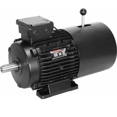
What are the key components of a typical brake motor system?
A typical brake motor system consists of several key components that work together to provide controlled stopping and holding capabilities. These components are carefully designed and integrated to ensure the efficient operation of the brake motor. Here's a detailed explanation of the key components of a typical brake motor system:
1. Electric Motor: The electric motor is the primary component of the brake motor system. It converts electrical energy into mechanical energy to drive the rotation of the equipment. The motor provides the necessary power and torque to perform the desired work. It can be an AC (alternating current) motor or a DC (direct current) motor, depending on the specific application requirements.
2. Braking Mechanism: The braking mechanism is a crucial component of the brake motor system that enables controlled stopping of the rotating equipment. It consists of various types of brakes, such as electromagnetic brakes or spring-loaded brakes. The braking mechanism engages when the power to the motor is cut off or the motor is de-energized, creating friction or applying pressure to halt the rotation.
3. Brake Coil or Actuator: In brake motors with electromagnetic brakes, a brake coil or actuator is employed. The coil generates a magnetic field when an electrical current passes through it, attracting the brake disc or plate and creating braking force. The coil is energized when the motor is powered, and it de-energizes when the power is cut off, allowing the brake to engage and stop the rotation.
4. Brake Disc or Plate: The brake disc or plate is a key component of the braking mechanism. It is attached to the motor shaft and rotates with it. When the brake engages, the disc or plate is pressed against a stationary surface, creating friction and stopping the rotation of the motor shaft. The material composition and design of the brake disc or plate are optimized for efficient braking performance.
5. Control System: Brake motor systems often incorporate a control system that enables precise control over the braking process. The control system allows for adjustable braking torque, response time, and braking profiles. It may include control devices such as switches, relays, or electronic control units (ECUs). The control system ensures the desired level of control and facilitates the integration of the brake motor system with other machinery or automation systems.
6. Power Supply: A reliable power supply is essential for the operation of the brake motor system. The power supply provides electrical energy to the motor and the brake mechanism. It can be a mains power supply or a dedicated power source, depending on the specific requirements of the application and the motor's power rating.
7. Mounting and Housing: Brake motors are typically housed in a sturdy enclosure that protects the components from environmental factors, such as dust, moisture, or vibration. The housing also provides mounting points for the motor and facilitates the connection of external devices or machinery. The design of the mounting and housing ensures the stability and safety of the brake motor system.
8. Optional Accessories: Depending on the application, a brake motor system may include optional accessories such as temperature sensors, shaft encoders, or position sensors. These accessories provide additional functionality and feedback, allowing for advanced control and monitoring of the brake motor system.
These are the key components of a typical brake motor system. The integration and interaction of these components ensure controlled stopping, load holding, and precise positioning capabilities, making brake motors suitable for a wide range of industrial applications.
editor by CX 2023-11-30
China Hot selling Sell Cycloid Hydraulic Motor, Hydraulic Planetary Gear Motor, Wholesale Rail Motor motor electric
Product Description
Product Overview
Introduction of hydraulic motor
The hydraulic motor is an executive component of the hydraulic system, which converts the liquid pressure energy provided by thehydraulic pump into the mechanical energy (torque and speed) of its output shaft. Liquid is the medium of transmitting force andmotion.
Radial piston hydraulic motor
The working principle of the radial piston type hydraulic motor is that when the pressure oil enters the bottom of the piston in the cylinder body through the window of the fixed oil distribution shaft 4, the piston extends outwards and firmly presses against the inner wall of the stator, because there is an eccentric distance between the stator and the cylinder block.
At the contact point between the plunger and the stator, the reaction force between the stator and the plunger is. The force can be decomposed into 2 components.
When the oil pressure acting on the bottom of the plunger is p, the diameter of the plunger is D, and the angle between the force and is x, the force produces a torque on the cylinder block and makes the cylinder block rotate. The cylinder block then outputs the torque and speed through the transmission shaft connected with the end face.
technical parameter
|
technical parameter
|
|||||||
|
Displacement(ml/r)
|
245
|
310
|
390
|
490
|
625
|
800
|
|
|
Flow(LPM)
|
Continuous
|
80
|
80
|
80
|
80
|
80
|
80
|
|
Intermittent
|
100
|
100
|
100
|
100
|
100
|
100
|
|
|
Speed(RPM)
|
Continuous
|
320
|
250
|
200
|
200
|
160
|
120
|
|
Intermittent
|
350
|
280
|
230
|
200
|
160
|
120
|
|
|
Pressure(Mps)
|
Continuous
|
14
|
14
|
14
|
14
|
12.5
|
10
|
|
Intermittent
|
15
|
15
|
15
|
15
|
13
|
12
|
|
|
Torque(N*m)
|
Continuous
|
400
|
500
|
550
|
680
|
780
|
800
|
|
Intermittent
|
420
|
520
|
580
|
700
|
800
|
820
|
|
Applicable models
Company profile
1.One set/Plastic box/Cardboard CTN
2.Safety for long-distance transportation
3.All of the productions will be checked carefully before delivery
Pre-sales Service
1. Inquiry and consulting support
2. Sample testing support
3. Recommend the most suitable machine according to customer's purpose
4. Factory visiting welcomed
After-sales Service
1. Training how to install the machine
2. Training how to use the machine
3. Warranty 1 year
4. Engineers available to service machinery oversea
FAQ
Q1.Are you a factory or a trading company?What can you provide?
We are a factory locates in industrial belt of HangZhou City,our main products are hydraulic orbit motors,hydraulic winches,hydraulic
steel hole punchers,mini excavators,etc.
Q2.I want to buy your product,how can I pay?
We support T/T,Paypal,Western Union,also you can pay by credit card.
Q3.How about the warranty?
We promise to supply high quality products and professional after-sales service.We can supply technical support as long as youneed,beyond that,we also offer 6 months of warranty.
Q4.If we don't find what we want on your website,what should we do?
You can start a conversation to us,or send us email about the descriptions and pictures of the products you need,we will check ifwe can supply and reply your inquiry ASAP.
Q5.Could we buy 1pcs of the item for quality testing?
Yes of course,we understand quality test is important and we are glad to send 1 set for quality testing.
| Certification: | ISO9001 |
|---|---|
| Excitation Mode: | Excited |
| Power Rating: | 1500W |
| Casing Protection: | Protection Type |
| Number of Poles: | 6 |
| Speed: | Low Speed |
| Samples: |
US$ 140/Piece
1 Piece(Min.Order) | |
|---|
| Customization: |
Available
| Customized Request |
|---|
The Basics of a Planetary Motor
A Planetary Motor is a type of gearmotor that uses multiple planetary gears to deliver torque. This system minimizes the chances of failure of individual gears and increases output capacity. Compared to the planetary motor, the spur gear motor is less complex and less expensive. However, a spur gear motor is generally more suitable for applications requiring low torque. This is because each gear is responsible for the entire load, limiting its torque.
Self-centering planetary gears
This self-centering mechanism for a planetary motor is based on a helical arrangement. The helical structure involves a sun-planet, with its crown and slope modified. The gears are mounted on a ring and share the load evenly. The helical arrangement can be either self-centering or self-resonant. This method is suited for both applications.
A helical planetary gear transmission is illustrated in FIG. 1. A helical configuration includes an output shaft 18 and a sun gear 18. The drive shaft extends through an opening in the cover to engage drive pins on the planet carriers. The drive shaft of the planetary gears can be fixed to the helical arrangement or can be removable. The transmission system is symmetrical, allowing the output shaft of the planetary motor to rotate radially in response to the forces acting on the planet gears.
A flexible pin can improve load sharing. This modification may decrease the face load distribution, but increases the (K_Hbeta) parameter. This effect affects the gear rating and life. It is important to understand the effects of flexible pins. It is worth noting that there are several other disadvantages of flexible pins in helical PGSs. The benefits of flexible pins are discussed below.
Using self-centering planetary gears for a helical planetary motor is essential for symmetrical force distribution. These gears ensure the symmetry of force distribution. They can also be used for self-centering applications. Self-centering planetary gears also guarantee the proper force distribution. They are used to drive a planetary motor. The gearhead is made of a ring gear, and the output shaft is supported by two ball bearings. Self-centering planetary gears can handle a high torque input, and can be suited for many applications.
To solve for a planetary gear mechanism, you need to find its pitch curve. The first step is to find the radius of the internal gear ring. A noncircular planetary gear mechanism should be able to satisfy constraints that can be complex and nonlinear. Using a computer, you can solve for these constraints by analyzing the profile of the planetary wheel's tooth curve.
High torque
Compared to the conventional planetary motors, high-torque planetary motors have a higher output torque and better transmission efficiency. The high-torque planetary motors are designed to withstand large loads and are used in many types of applications, such as medical equipment and miniature consumer electronics. Their compact design makes them suitable for small space-saving applications. In addition, these motors are designed for high-speed operation.
They come with a variety of shaft configurations and have a wide range of price-performance ratios. The FAULHABER planetary gearboxes are made of plastic, resulting in a good price-performance ratio. In addition, plastic input stage gears are used in applications requiring high torques, and steel input stage gears are available for higher speeds. For difficult operating conditions, modified lubrication is available.
Various planetary gear motors are available in different sizes and power levels. Generally, planetary gear motors are made of steel, brass, or plastic, though some use plastic for their gears. Steel-cut gears are the most durable, and are ideal for applications that require a high amount of torque. Similarly, nickel-steel gears are more lubricated and can withstand a high amount of wear.
The output torque of a high-torque planetary gearbox depends on its rated input speed. Industrial-grade high-torque planetary gearboxes are capable of up to 18000 RPM. Their output torque is not higher than 2000 nm. They are also used in machines where a planet is decelerating. Their working temperature ranges between 25 and 100 degrees Celsius. For best results, it is best to choose the right size for the application.
A high-torque planetary gearbox is the most suitable type of high-torque planetary motor. It is important to determine the deceleration ratio before buying one. If there is no product catalog that matches your servo motor, consider buying a close-fitting high-torque planetary gearbox. There are also high-torque planetary gearboxes available for custom-made applications.
High efficiency
A planetary gearbox is a type of mechanical device that is used for high-torque transmission. This gearbox is made of multiple pairs of gears. Large gears on the output shaft mesh with small gears on the input shaft. The ratio between the big and small gear teeth determines the transmittable torque. High-efficiency planetary gearheads are available for linear motion, axial loads, and sterilizable applications.
The AG2400 high-end gear unit series is ideally matched to Beckhoff's extensive line of servomotors and gearboxes. Its single-stage and multi-stage transmission ratios are highly flexible and can be matched to different robot types. Its modified lubrication helps it operate in difficult operating conditions. These high-performance gear units are available in a wide range of sizes.
A planetary gear motor can be made of steel, nickel-steel, or brass. In addition to steel, some models use plastic. The planetary gears share work between multiple gears, making it easy to transfer high amounts of power without putting a lot of stress on the gears. The gears in a planetary gear motor are held together by a movable arm. High-efficiency planetary gear motors are more efficient than traditional gearmotors.
While a planetary gear motor can generate torque, it is more efficient and cheaper to produce. The planetary gear system is designed with all gears operating in synchrony, minimizing the chance of a single gear failure. The efficiency of a planetary gearmotor makes it a popular choice for high-torque applications. This type of motor is suitable for many applications, and is less expensive than a standard geared motor.
The planetary gearbox is a combination of a planetary type gearbox and a DC motor. The planetary gearbox is compact, versatile, and efficient, and can be used in a wide range of industrial environments. The planetary gearbox with an HN210 DC motor is used in a 22mm OD, PPH, and ph configuration with voltage operating between 6V and 24V. It is available in many configurations and can be custom-made to meet your application requirements.
High cost
In general, planetary gearmotors are more expensive than other configurations of gearmotors. This is due to the complexity of their design, which involves the use of a central sun gear and a set of planetary gears which mesh with each other. The entire assembly is enclosed in a larger internal tooth gear. However, planetary motors are more effective for higher load requirements. The cost of planetary motors varies depending on the number of gears and the number of planetary gears in the system.
If you want to build a planetary gearbox, you can purchase a gearbox for the motor. These gearboxes are often available with several ratios, and you can use any one to create a custom ratio. The cost of a gearbox depends on how much power you want to move with the gearbox, and how much gear ratio you need. You can even contact your local FRC team to purchase a gearbox for the motor.
Gearboxes play a major role in determining the efficiency of a planetary gearmotor. The output shafts used for this type of motor are usually made of steel or nickel-steel, while those used in planetary gearboxes are made from brass or plastic. The former is the most durable and is best for applications that require high torque. The latter, however, is more absorbent and is better at holding lubricant.
Using a planetary gearbox will allow you to reduce the input power required for the stepper motor. However, this is not without its downsides. A planetary gearbox can also be replaced with a spare part. A planetary gearbox is inexpensive, and its spare parts are inexpensive. A planetary gearbox has low cost compared to a planetary motor. Its advantages make it more desirable in certain applications.
Another advantage of a planetary gear unit is the ability to handle ultra-low speeds. Using a planetary gearbox allows stepper motors to avoid resonance zones, which can cause them to crawl. In addition, the planetary gear unit allows for safe and efficient cleaning. So, whether you're considering a planetary gear unit for a particular application, these gear units can help you get exactly what you need.
editor by CX
2023-04-14
China Sales Eaton Original Hydraulic Motor Bm Hydraulic Cycloid Planetary Gear Motor Manufacturers with Best Sales
Item Description
Solution Overview
Introduction of hydraulic motor
The hydraulic motor is an executive ingredient of the hydraulic system, which converts the liquid stress strength supplied by thehydraulic pump into the mechanical energy (torque and speed) of its output shaft. Liquid is the medium of transmitting power andmotion.
Radial piston hydraulic motor
The working principle of the radial piston kind hydraulic motor is that when the force oil enters the base of the piston in the cylinder entire body by way of the window of the fastened oil distribution shaft 4, the piston extends outwards and firmly presses towards the internal wall of the stator, simply because there is an eccentric distance among the stator and the cylinder block.
At the make contact with stage in between the plunger and the stator, the reaction power among the stator and the plunger is. The power can be decomposed into 2 factors.
When the oil stress acting on the base of the plunger is p, the diameter of the plunger is D, and the angle in between the drive and is x, the pressure generates a torque on the cylinder block and makes the cylinder block rotate. The cylinder block then outputs the torque and velocity through the transmission shaft linked with the stop encounter.
specialized parameter
|
technological parameter
|
|||||||
|
Displacement(ml/r)
|
245
|
310
|
390
|
490
|
625
|
800
|
|
|
Stream(LPM)
|
Continuous
|
80
|
eighty
|
80
|
80
|
eighty
|
eighty
|
|
Intermittent
|
100
|
100
|
a hundred
|
a hundred
|
a hundred
|
one hundred
|
|
|
Pace(RPM)
|
Constant
|
320
|
250
|
200
|
two hundred
|
one hundred sixty
|
one hundred twenty
|
|
Intermittent
|
350
|
280
|
230
|
two hundred
|
one hundred sixty
|
one hundred twenty
|
|
|
Pressure(Mps)
|
Ongoing
|
14
|
fourteen
|
fourteen
|
14
|
12.five
|
10
|
|
Intermittent
|
15
|
15
|
fifteen
|
15
|
13
|
12
|
|
|
Torque(N*m)
|
Continuous
|
four hundred
|
five hundred
|
550
|
680
|
780
|
800
|
|
Intermittent
|
420
|
520
|
580
|
seven hundred
|
800
|
820
|
|
Relevant models
Organization profile
one.One established/Plastic box/Cardboard CTN
two.Protection for extended-length transportation
3.All of the productions will be checked meticulously prior to shipping and delivery
Pre-product sales Services
1. Inquiry and consulting help
2. Sample tests assistance
3. Advise the most suited equipment according to customer's purpose
4. Manufacturing facility checking out welcomed
Right after-product sales Support
1. Training how to put in the machine
2. Instruction how to use the machine
three. Warranty 1 calendar year
4. Engineers offered to service machinery oversea
FAQ
Q1.Are you a manufacturing facility or a buying and selling business?What can you supply?
We are a manufacturing facility locates in industrial belt of HangZhou City,our primary products are hydraulic orbit motors,hydraulic winches,hydraulic
steel hole punchers,mini excavators,and many others.
Q2.I want to get your product,how can I pay out?
We help T/T,Paypal,Western Union,also you can spend by credit card.
Q3.How about the warranty?
We promise to offer substantial top quality merchandise and professional after-income service.We can offer specialized assist as prolonged as youneed,outside of that,we also offer you 6 months of guarantee.
Q4.If we don't find what we want on your website,what ought to we do?
You can commence a discussion to us,or send us electronic mail about the descriptions and photographs of the goods you want,we will examine ifwe can provide and reply your inquiry ASAP.
Q5.Could we buy 1pcs of the product for good quality screening?
Indeed of program,we comprehend high quality test is critical and we are happy to ship 1 set for quality tests.
| Certification: | ISO9001 |
|---|---|
| Excitation Mode: | Excited |
| Power Rating: | 1500W |
| Casing Protection: | Protection Type |
| Number of Poles: | 6 |
| Speed: | Low Speed |
###
| Samples: |
US$ 140/Piece
1 Piece(Min.Order) |
|---|
###
| Customization: |
Available
|
|---|
###
|
technical parameter
|
|||||||
|
Displacement(ml/r)
|
245
|
310
|
390
|
490
|
625
|
800
|
|
|
Flow(LPM)
|
Continuous
|
80
|
80
|
80
|
80
|
80
|
80
|
|
Intermittent
|
100
|
100
|
100
|
100
|
100
|
100
|
|
|
Speed(RPM)
|
Continuous
|
320
|
250
|
200
|
200
|
160
|
120
|
|
Intermittent
|
350
|
280
|
230
|
200
|
160
|
120
|
|
|
Pressure(Mps)
|
Continuous
|
14
|
14
|
14
|
14
|
12.5
|
10
|
|
Intermittent
|
15
|
15
|
15
|
15
|
13
|
12
|
|
|
Torque(N*m)
|
Continuous
|
400
|
500
|
550
|
680
|
780
|
800
|
|
Intermittent
|
420
|
520
|
580
|
700
|
800
|
820
|
|
###
What Is a Gear Motor?
A gear motor is an electric motor coupled with a gear train. It uses either DC or AC power to achieve its purpose. The primary benefit of a gear reducer is its ability to multiply torque while maintaining a compact size. The trade-off of this additional torque comes in the form of a reduced output shaft speed and overall efficiency. However, proper gear technology and ratios provide optimum output and speed profiles. This type of motor unlocks the full potential of OEM equipment.
Inertial load
Inertial load on a gear motor is the amount of force a rotating device produces due to its inverse square relationship with its inertia. The greater the inertia, the less torque can be produced by the gear motor. However, if the inertia is too high, it can cause problems with positioning, settling time, and controlling torque and velocity. Gear ratios should be selected for optimal power transfer.
The duration of acceleration and braking time of a gear motor depends on the type of driven load. An inertia load requires longer acceleration time whereas a friction load requires breakaway torque to start the load and maintain it at its desired speed. Too short a time period can cause excessive gear loading and may result in damaged gears. A safe approach is to disconnect the load when power is disconnected to prevent inertia from driving back through the output shaft.
Inertia is a fundamental concept in the design of motors and drive systems. The ratio of mass and inertia of a load to a motor determines how well the motor can control its speed during acceleration or deceleration. The mass moment of inertia, also called rotational inertia, is dependent on the mass, geometry, and center of mass of an object.
Applications
There are many applications of gear motors. They provide a powerful yet efficient means of speed and torque control. They can be either AC or DC, and the two most common motor types are the three-phase asynchronous and the permanent magnet synchronous servomotor. The type of motor used for a given application will determine its cost, reliability, and complexity. Gear motors are typically used in applications where high torque is required and space or power constraints are significant.
There are two types of gear motors. Depending on the ratio, each gear has an output shaft and an input shaft. Gear motors use hydraulic pressure to produce torque. The pressure builds on one side of the motor until it generates enough torque to power a rotating load. This type of motors is not recommended for applications where load reversals occur, as the holding torque will diminish with age and shaft vibration. However, it can be used for precision applications.
The market landscape shows the competitive environment of the gear motor industry. This report also highlights key items, income and value creation by region and country. The report also examines the competitive landscape by region, including the United States, China, India, the GCC, South Africa, Brazil, and the rest of the world. It is important to note that the report contains segment-specific information, so that readers can easily understand the market potential of the geared motors market.
Size
The safety factor, or SF, of a gear motor is an important consideration when selecting one for a particular application. It compensates for the stresses placed on the gearing and enables it to run at maximum efficiency. Manufacturers provide tables detailing typical applications, with multiplication factors for duty. A gear motor with a SF of three or more is suitable for difficult applications, while a gearmotor with a SF of one or two is suitable for relatively easy applications.
The global gear motor market is highly fragmented, with numerous small players catering to various end-use industries. The report identifies various industry trends and provides comprehensive information on the market. It outlines historical data and offers valuable insights on the industry. The report also employs several methodologies and approaches to analyze the market. In addition to providing historical data, it includes detailed information by market segment. In-depth analysis of market segments is provided to help identify which technologies will be most suitable for which applications.
Cost
A gear motor is an electric motor that is paired with a gear train. They are available in AC or DC power systems. Compared to conventional motors, gear reducers can maximize torque while maintaining compact dimensions. But the trade-off is the reduced output shaft speed and overall efficiency. However, when used correctly, a gear motor can produce optimal output and mechanical fit. To understand how a gear motor works, let's look at two types: right-angle geared motors and inline geared motors. The first two types are usually used in automation equipment and in agricultural and medical applications. The latter type is designed for rugged applications.
In addition to its efficiency, DC gear motors are space-saving and have low energy consumption. They can be used in a number of applications including money counters and printers. Automatic window machines and curtains, glass curtain walls, and banknote vending machines are some of the other major applications of these motors. They can cost up to 10 horsepower, which is a lot for an industrial machine. However, these are not all-out expensive.
Electric gear motors are versatile and widely used. However, they do not work well in applications requiring high shaft speed and torque. Examples of these include conveyor drives, frozen beverage machines, and medical tools. These applications require high shaft speed, so gear motors are not ideal for these applications. However, if noise and other problems are not a concern, a motor-only solution may be the better choice. This way, you can use a single motor for multiple applications.
Maintenance
Geared motors are among the most common equipment used for drive trains. Proper maintenance can prevent damage and maximize their efficiency. A guide to gear motor maintenance is available from WEG. To prevent further damage, follow these maintenance steps:
Regularly check electrical connections. Check for loose connections and torque them to the recommended values. Also, check the contacts and relays to make sure they are not tangled or damaged. Check the environment around the gear motor to prevent dust from clogging the passageway of electric current. A proper maintenance plan will help you identify problems and extend their life. The manual will also tell you about any problems with the gearmotor. However, this is not enough - it is important to check the condition of the gearbox and its parts.
Conduct visual inspection. The purpose of visual inspection is to note any irregularities that may indicate possible problems with the gear motor. A dirty motor may be an indication of a rough environment and a lot of problems. You can also perform a smell test. If you can smell a burned odor coming from the windings, there may be an overheating problem. Overheating can cause the windings to burn and damage.
Reactive maintenance is the most common method of motor maintenance. In this type of maintenance, you only perform repairs if the motor stops working due to a malfunction. Regular inspection is necessary to avoid unexpected motor failures. By using a logbook to document motor operations, you can determine when it is time to replace the gear motor. In contrast to preventive maintenance, reactive maintenance requires no regular tests or services. However, it is recommended to perform inspections every six months.
editor by czh 2023-01-06
China BN Excavator GFT9T2B38 REXROTH GFT PLANETARY with HYDRAULIC MOTOR A10VE45 motor driver
Product Description
BN Excavator GFT9T2B38 CZPT GFT PLANETARY with HYDRAULIC MOTOR A10VE45
|
PART NAME |
REXROTH GFT PLANETARY with HYDRAULIC MOTOR A10VE45 |
|
EQUIPMENT |
apply to REXROTH GFT9T2B38 EXCAVATOR |
|
MOTOR NO. |
A10VE45 |
|
STOCK CODE |
9209608 |
|
CATEGORY |
Construction Machinery Parts, Excavator Spare Parts |
|
INSTALLATION |
POWER TRAIN |
|
APPLICATION |
Replacement |
|
ITEM CONDITION |
NEW |
|
LOGO |
BN |
|
MOQ |
1 pc |
DESCRIPTION:
1. Completely, assembly, and ready to installed in your REXROTH GFT9T2B38 excavators.
2. Without MOTOR, already been installed the MOTOR HOUSING & MOTOR SHAFT
3. All components are produced by us.
4. All new, undamaged.
5. Painted or Unpainted, depend on requirement
6. 90 days warranty, call or email with any questions.
7. Plywood Case Packing, free of fumigation
8. Deliver to worldwide by Sea, Air, or Carrier.
- We are the manufacturer and own 18000 m2 factory areas, good relationship with material suppliers, which make more competitive price and steady quality.
- We have more than 80 units advanced facilities for production.
- We have 8 senior engineers with more than 30 years experience on designing and machining.
- Our sales term offer the efficient service for every customers.
- We are the long term parts supplier for many famous companies, such as FOSTER WHEELER POWER MACHINERY CO.,LTD and C.R.Dinly etc.
- We develop spare parts for old and new excavator models, and submit our latest products to customers every month so that to meet the market demand.
- We have high market share in Oversea market and Domestic market, Southeast Asia 60%, Russia 10%, Middle East 8%, North and South America 10%,Europe 8%, others 4%.
|
TRADE TERMS |
EXW, FOB, CFR, CIF |
|
PAYMENT TERMS |
T/T, Western Union, Alipay, Paypal |
|
PORT |
HangZhou Port, negotiation |
|
LEAD TIME |
|
|
DELIVERY |
By Sea, Air, Carrier |
|
ORDER FLOW |
|
1. Warranty Type: We will replace the product which have quality problem.
2. Warranty Period:
Supply 3 months warranty for the products from the date of arrival. Customer should check the items according to the order list after arrival. Contact with us and offer the data, photos of the problem items.
3. You need to pay for the replacement charge for following condition:
* Wrong Order from customer.
* Natural Disasters cause the damage.
* Error installation.
* The machine and reducer work over time and over load.
* Lost by any condition.
* Xihu (West Lake) Dis.n element destroyed.
* Corrode with rust during stock and running.
* Warranty Expired.
4. Others
They are the product easy to be rust away, please wrap them well. We just supply warranty for the products we are producing, except the Bearing, Seal, and some others we mention before order.If there is any problem about the products, installation or maintenance, please contact with us any time. We reserve the rights of final interpretation.
|
US $1,100-1,200 / Piece | |
1 Piece (Min. Order) |
###
| Type: | GEARBOX |
|---|---|
| Application: | Excavator |
| Certification: | SGS |
| Condition: | New |
| Category: | Construction Machinery Parts |
| Model: | Apply to REXROTH GFT9T2B38 |
###
| Customization: |
Available
|
|---|
###
|
PART NAME |
REXROTH GFT PLANETARY with HYDRAULIC MOTOR A10VE45 |
|
EQUIPMENT |
apply to REXROTH GFT9T2B38 EXCAVATOR |
|
MOTOR NO. |
A10VE45 |
|
STOCK CODE |
9209608 |
|
CATEGORY |
Construction Machinery Parts, Excavator Spare Parts |
|
INSTALLATION |
POWER TRAIN |
|
APPLICATION |
Replacement |
|
ITEM CONDITION |
NEW |
|
LOGO |
BN |
|
MOQ |
1 pc |
###
|
TRADE TERMS |
EXW, FOB, CFR, CIF |
|
PAYMENT TERMS |
T/T, Western Union, Alipay, Paypal |
|
PORT |
Jiangmen Port, negotiation |
|
LEAD TIME |
|
|
DELIVERY |
By Sea, Air, Carrier |
|
ORDER FLOW |
|
|
US $1,100-1,200 / Piece | |
1 Piece (Min. Order) |
###
| Type: | GEARBOX |
|---|---|
| Application: | Excavator |
| Certification: | SGS |
| Condition: | New |
| Category: | Construction Machinery Parts |
| Model: | Apply to REXROTH GFT9T2B38 |
###
| Customization: |
Available
|
|---|
###
|
PART NAME |
REXROTH GFT PLANETARY with HYDRAULIC MOTOR A10VE45 |
|
EQUIPMENT |
apply to REXROTH GFT9T2B38 EXCAVATOR |
|
MOTOR NO. |
A10VE45 |
|
STOCK CODE |
9209608 |
|
CATEGORY |
Construction Machinery Parts, Excavator Spare Parts |
|
INSTALLATION |
POWER TRAIN |
|
APPLICATION |
Replacement |
|
ITEM CONDITION |
NEW |
|
LOGO |
BN |
|
MOQ |
1 pc |
###
|
TRADE TERMS |
EXW, FOB, CFR, CIF |
|
PAYMENT TERMS |
T/T, Western Union, Alipay, Paypal |
|
PORT |
Jiangmen Port, negotiation |
|
LEAD TIME |
|
|
DELIVERY |
By Sea, Air, Carrier |
|
ORDER FLOW |
|
How to Select a Gear Motor
A gearmotor is an electrical machine that transfers energy from one place to another. There are many types of gearmotors. This article will discuss the types of gearmotors, including Angular geared motors, Planetary gearboxes, Hydraulic gear motors, and Croise motors. In addition to its uses, gearmotors have many different characteristics. In addition, each type has distinct advantages and disadvantages. Listed below are a few tips on selecting a gearmotor.
Angular geared motors
Angular geared motors are the optimum drive element for applications where torques, forces, and motions need to be transferred at an angle. Compared to other types of geared motors, these have few moving parts, a compact design, and a long life. Angular geared motors are also highly efficient in travel drive applications. In addition to their durability, they have a low maintenance requirement and are highly corrosion-resistant.
Helical worm geared motors are a low-cost solution for drives that employ angular geared motors. They combine a worm gear stage and helical input stage to offer higher efficiency than pure worm geared motors. This drive solution is highly reliable and noise-free. Angular geared motors are often used in applications where noise is an issue, and helical worm geared motors are particularly quiet.
The gear ratio of an angular geared motor depends on the ratio between its input and output shaft. A high-quality helical geared motor has a relatively low mechanical noise level, and can be installed in almost any space. The torque of a helical geared motor can be measured by using frequency measurement equipment. The energy efficiency of angular geared motors is one of the most important factors when choosing a motor. Its symmetrical arrangement also allows it to operate in low-speed environments.
When selecting the right angular geared motor, it is important to keep in mind that increased torque will lead to poor output performance. Once a gear motor reaches its stall torque, it will no longer function properly. This makes it important to consult a performance curve to choose the appropriate motor. Most DC motor manufacturers are more than happy to provide these to customers upon request. Angular geared motors are more expensive than conventional worm gear motors.
Planetary gearboxes
Planetary gearboxes are used in industrial machinery to generate higher torque and power density. There are three main types of planetary gearboxes: double stage, triple stage, and multistage. The central sun gear transfers torque to a group of planetary gears, while the outer ring and spindle provide drive to the motor. The design of planetary gearboxes delivers up to 97% of the power input.
The compact size of planetary gears results in excellent heat dissipation. In some applications, lubrication is necessary to improve durability. Nevertheless, if you are looking for high speed transmission, you should consider the additional features, such as low noise, corrosion resistance, and construction. Some constructors are better than others. Some are quick to respond, while others are unable to ship their products in a timely fashion.
The main benefit of a planetary gearbox is its compact design. Its lightweight design makes it easy to install, and the efficiency of planetary gearboxes is up to 0.98%. Another benefit of planetary gearboxes is their high torque capacity. These gearboxes are also able to work in applications with limited space. Most modern automatic transmissions in the automotive industry use planetary gears.
In addition to being low in cost, planetary gearboxes are a great choice for many applications. Neugart offers both compact and right angle versions. The right angle design offers a high power-to-weight ratio, making it ideal for applications where torque is needed to be transmitted in reverse mode. So if you're looking for an efficient way to move heavy machinery around, planetary gearboxes can be a great choice.
Another advantage of planetary gearboxes is their ability to be easily and rapidly changed from one application to another. Since planetary gears are designed to be flexible, you don't have to buy new ones if you need to change gear ratios. You can also use planetary gears in different industries and save on safety stock by sharing common parts. These gears are able to withstand high shock loads and demanding conditions.
Hydraulic gear motors
Hydraulic gear motors are driven by oil that is pumped into a gear box and causes the gears to rotate. This method of energy production is quiet and inexpensive. The main drawbacks of hydraulic gear motors are that they are noisy and inefficient at low speeds. The other two types of hydraulic motors are piston and vane-type hydraulic motors. The following are some common benefits of hydraulic gear motors.
A hydraulic gear motor is composed of two gears - a driven gear and an idler. The driven gear is attached to the output shaft via a key. High-pressure oil flows into the housing between the gear tips and the motor housing, and the oil then exits through an outlet port. Unlike a conventional gear motor, the gears mesh to prevent the oil from flowing backward. As a result, they are an excellent choice for agricultural and industrial applications.
The most common hydraulic gear motors feature a gerotor and a drive gear. These gears mesh with a larger gear to produce rotation. There are also three basic variations of gear motors: roller-gerotor, gerotor, and differential. The latter produces higher torque and less friction than the previous two. These differences make it difficult to choose which type is the best for your needs. A high-performance gear motor will last longer than an ordinary one.
Radial piston hydraulic motors operate in the opposite direction to the reciprocating shaft of an electric gearmotor. They have nine pistons arranged around a common center line. Fluid pressure causes the pistons to reciprocate, and when they are stationary, the pistons push the fluid out and move back in. Because of the high pressure created by the fluid, they can rotate at speeds up to 25,000RPM. In addition, hydraulic gear motors are highly efficient, allowing them to be used in a wide range of industrial and commercial applications.
Hydraulic gear motors complement hydraulic pumps and motors. They are also available in reversible models. To choose the right hydraulic motor for your project, take time to gather all the necessary information about the installation process. Some types require specialized expertise or complicated installation. Also, there are some differences between closed and open-loop hydraulic motors. Make sure to discuss the options with a professional before you make a decision.
Croise motors
There are many advantages to choosing a Croise gear motor. It is highly compact, with less weight and space than standard motors. Its right-angle shaft and worm gear provide smooth, quiet operation. A silent-type brake ensures no metallic sound during operation. It also offers excellent positioning accuracy and shock resistance. This is why this motor is ideal for high-frequency applications. Let's take a closer look.
A properly matched gearmotor will provide maximum torque output in a specified period. Its maximum developing torque is typically the rated output torque. A one-twelfth-horsepower (1/8 horsepower) motor can meet torque requirements of six inch-pounds, without exceeding its breakdown rating. This lower-cost unit allows for production variations and allows the customer to use a less powerful motor. Croise gear motors are available in a variety of styles.
editor by czh 2022-11-28
China Good quality Expert Manufacturer of Hydraulic Psiton Motor CZPT Ms Mse Series Low Speed High Torque for Sale with Great quality
Product Description
Helm Tower Main products : Poclain hydraulic motor MS02 MSE02 MS05 MSE05 MS08 MSE08 MS11 MSE11 MS18 MSE18 MS25 MS35 MS50 MS83 MS125 OEM manufacturer.
For instance:
- BELL 220A Telelogger
- CZPT 4011 Road Roller
- BOMAG 211 Soil compactor
- BOMAG 130 AD Road Roller
- BOMAG Roller BW213 D2
- Carterpillar 226B
- Carterpillar CS-563 compactor
- John Deere 280 skid steer,
- T190 skid steer and excavators
- VERMEER Horizontal Directional Drill
- SANDVIK Machine
- Gehl 6635 Skid steer
- Greenbeans and pea Harvesting Machine(PMC-979-AT)
HangZhou CZPT NODA HYDRAULIC CO.,LTD
P.C:315207
Website:nbht2011
| Model | displacement (ml/rpm) | rated pressure (MPa) |
maximum pressure (MPa) |
rated pitch of strand(N. m) (whole displacement) |
speed range (rpm) |
maximum power(kw) (whole displacement) |
|
| whole displacement | semi-displacement | ||||||
| MS02 | 213 | 25 | 40 | 796 | 0-310 | 16 | |
| MS05 | 468 | 234 | 25 | 40 | 1749 | 0-200 | 25 |
| MS08 | 780 | 390 | 25 | 40 | 2914 | 0-170 | 36 |
| MS11 | 1048 | 524 | 25 | 40 | 3916 | 0-160 | 44 |
| MS18 | 1747 | 873 | 25 | 40 | 6528 | 0-150 | 62 |
| MS25 | 2498 | 1249 | 25 | 40 | 9334 | 0-130 | 80 |
| MS35 | 3494 | 1747 | 25 | 40 | 13055 | 0-100 | 97 |
| MS50 | 4996 | 2498 | 25 | 40 | 18667 | 0-100 | 123 |
| MS83 | 8328 | 4164 | 25 | 40 | 31098 | 0-80 | 176 |
| MS125 | 12500 | 6250 | 25 | 40 | 19875 | 0-50 | 240 |
Dynamic Modeling of a Planetary Motor
A planetary gear motor consists of a series of gears rotating in perfect synchrony, allowing them to deliver torque in a higher output capacity than a spur gear motor. Unlike the planetary motor, spur gear motors are simpler to build and cost less, but they are better for applications requiring lower torque output. That is because each gear carries the entire load. The following are some key differences between the two types of gearmotors.
planetary gear system
A planetary gear transmission is a type of gear mechanism that transfers torque from one source to another, usually a rotary motion. Moreover, this type of gear transmission requires dynamic modeling to investigate its durability and reliability. Previous studies included both uncoupled and coupled meshing models for the analysis of planetary gear transmission. The combined model considers both the shaft structural stiffness and the bearing support stiffness. In some applications, the flexible planetary gear may affect the dynamic response of the system.
In a planetary gear device, the axial end surface of the cylindrical portion is rotatable relative to the separating plate. This mechanism retains lubricant. It is also capable of preventing foreign particles from entering the planetary gear system. A planetary gear device is a great choice if your planetary motor's speed is high. A high-quality planetary gear system can provide a superior performance than conventional systems.
A planetary gear system is a complex mechanism, involving three moving links that are connected to each other through joints. The sun gear acts as an input and the planet gears act as outputs. They rotate about their axes at a ratio determined by the number of teeth on each gear. The sun gear has 24 teeth, while the planet gears have three-quarters that ratio. This ratio makes a planetary motor extremely efficient.
planetary gear train
To predict the free vibration response of a planetary motor gear train, it is essential to develop a mathematical model for the system. Previously, static and dynamic models were used to study the behavior of planetary motor gear trains. In this study, a dynamic model was developed to investigate the effects of key design parameters on the vibratory response. Key parameters for planetary gear transmissions include the structure stiffness and mesh stiffness, and the mass and location of the shaft and bearing supports.
The design of the planetary motor gear train consists of several stages that can run with variable input speeds. The design of the gear train enables the transmission of high torques by dividing the load across multiple planetary gears. In addition, the planetary gear train has multiple teeth which mesh simultaneously in operation. This design also allows for higher efficiency and transmittable torque. Here are some other advantages of planetary motor gear trains. All these advantages make planetary motor gear trains one of the most popular types of planetary motors.
The compact footprint of planetary gears allows for excellent heat dissipation. High speeds and sustained performances will require lubrication. This lubricant can also reduce noise and vibration. But if these characteristics are not desirable for your application, you can choose a different gear type. Alternatively, if you want to maintain high performance, a planetary motor gear train will be the best choice. So, what are the advantages of planetary motor gears?
planetary gear train with fixed carrier train ratio
The planetary gear train is a common type of transmission in various machines. Its main advantages are high efficiency, compactness, large transmission ratio, and power-to-weight ratio. This type of gear train is a combination of spur gears, single-helical gears, and herringbone gears. Herringbone planetary gears have lower axial force and high load carrying capacity. Herringbone planetary gears are commonly used in heavy machinery and transmissions of large vehicles.
To use a planetary gear train with a fixed carrier train ratio, the first and second planets must be in a carrier position. The first planet is rotated so that its teeth mesh with the sun's. The second planet, however, cannot rotate. It must be in a carrier position so that it can mesh with the sun. This requires a high degree of precision, so the planetary gear train is usually made of multiple sets. A little analysis will simplify this design.
The planetary gear train is made up of three components. The outer ring gear is supported by a ring gear. Each gear is positioned at a specific angle relative to one another. This allows the gears to rotate at a fixed rate while transferring the motion. This design is also popular in bicycles and other small vehicles. If the planetary gear train has several stages, multiple ring gears may be shared. A stationary ring gear is also used in pencil sharpener mechanisms. Planet gears are extended into cylindrical cutters. The ring gear is stationary and the planet gears rotate around a sun axis. In the case of this design, the outer ring gear will have a -3/2 planet gear ratio.
planetary gear train with zero helix angle
The torque distribution in a planetary gear is skewed, and this will drastically reduce the load carrying capacity of a needle bearing, and therefore the life of the bearing. To better understand how this can affect a gear train, we will examine two studies conducted on the load distribution of a planetary gear with a zero helix angle. The first study was done with a highly specialized program from the bearing manufacturer INA/FAG. The red line represents the load distribution along a needle roller in a zero helix gear, while the green line corresponds to the same distribution of loads in a 15 degree helix angle gear.
Another method for determining a gear's helix angle is to consider the ratio of the sun and planet gears. While the sun gear is normally on the input side, the planet gears are on the output side. The sun gear is stationary. The two gears are in engagement with a ring gear that rotates 45 degrees clockwise. Both gears are attached to pins that support the planet gears. In the figure below, you can see the tangential and axial gear mesh forces on a planetary gear train.
Another method used for calculating power loss in a planetary gear train is the use of an auto transmission. This type of gear provides balanced performance in both power efficiency and load capacity. Despite the complexities, this method provides a more accurate analysis of how the helix angle affects power loss in a planetary gear train. If you're interested in reducing the power loss of a planetary gear train, read on!
planetary gear train with spur gears
A planetary gearset is a type of mechanical drive system that uses spur gears that move in opposite directions within a plane. Spur gears are one of the more basic types of gears, as they don't require any specialty cuts or angles to work. Instead, spur gears use a complex tooth shape to determine where the teeth will make contact. This in turn, will determine the amount of power, torque, and speed they can produce.
A two-stage planetary gear train with spur gears is also possible to run at variable input speeds. For such a setup, a mathematical model of the gear train is developed. Simulation of the dynamic behaviour highlights the non-stationary effects, and the results are in good agreement with the experimental data. As the ratio of spur gears to spur gears is not constant, it is called a dedendum.
A planetary gear train with spur gears is a type of epicyclic gear train. In this case, spur gears run between gears that contain both internal and external teeth. The circumferential motion of the spur gears is analogous to the rotation of planets in the solar system. There are four main components of a planetary gear train. The planet gear is positioned inside the sun gear and rotates to transfer motion to the sun gear. The planet gears are mounted on a joint carrier that is connected to the output shaft.
planetary gear train with helical gears
A planetary gear train with helical teeth is an extremely powerful transmission system that can provide high levels of power density. Helical gears are used to increase efficiency by providing a more efficient alternative to conventional worm gears. This type of transmission has the potential to improve the overall performance of a system, and its benefits extend far beyond the power density. But what makes this transmission system so appealing? What are the key factors to consider when designing this type of transmission system?
The most basic planetary train consists of the sun gear, planet gear, and ring gear elements. The number of planets varies, but the basic structure of planetary gears is similar. A simple planetary geartrain has the sun gear driving a carrier assembly. The number of planets can be as low as two or as high as six. A planetary gear train has a low mass inertia and is compact and reliable.
The mesh phase properties of a planetary gear train are particularly important in designing the profiles. Various parameters such as mesh phase difference and tooth profile modifications must be studied in depth in order to fully understand the dynamic characteristics of a PGT. These factors, together with others, determine the helical gears' performance. It is therefore essential to understand the mesh phase of a planetary gear train to design it effectively.
150 made in China - replacement parts - in Al-Raqqa Syrian Arab Republic Tph High Efficiency Hydraulic Cone Crusher Price with ce certificate top quality low price


We - EPG Group the bigge EPT Chain and agricultural gearbox manufacturing facility in China with 5 different branches. For much more details: Mobile/whatsapp/telegram/Kakao us at: 0086~13083988828 13858117778 0571 88828
Solution Introduction
GPY series solitary-cylinder cone crusher developed and manufactured by our organization is currently the mo EPT advanced cone crusher in whole China. It aims at the higher conclude industry and is built-in with the innovative mechanical, electrical and hydraulic technologies as a whole, which achieves the perfect crushing performance. It functions in robu EPT casting steel frame, forged alloy major shaft, and high accurate arc gear transmission system. Combined with one particular appropriate crushing chamber from all optiona EPT and PLC automated control program, the cone crusher could fully enjoy its overall performance and advantages. It is extensively utilized for the wonderful and coarse crushing of various sort of stones and minerals, which features in higher crushing performance, and could fulfills diverse crushing need for our clientele.
Complex Parameters
| Model | ECC. mm |
Feed opening(mm) | Power kw | CSS(mm)/ Throughput Capacity(t/h) | |||||||||||
| EF | F | MF | M | C | EC | 8mm | 10mm | 15mm | 20mm | 25mm | 30mm | 35mm | |||
| GPY100 | twenty | 40 | 50 | 100 | 130 | 150 | 90 | 45-fifty | 45-55 | 65-seventy five | ninety-100 | ||||
| twenty five | 50-60 | 70-85 | one hundred-a hundred and fifteen | ||||||||||||
| GPY200 | twenty five | 70 | 130 | 210 | 160 | 85-105 | 105-125 | a hundred twenty five-one hundred fifty | one hundred fifty five-a hundred seventy five | 180-205 | |||||
| 32 | 135-a hundred and fifty five | 165-185 | 185-215 | ||||||||||||
| GPY300 | 32 | 60 | 100 | 130 | 180 | 260 | 250 | one hundred-200 | a hundred and ten-a hundred and forty | 155-185 | 185-215 | 220-250 | 255-285 | 290-320 | |
| 40 | 140-a hundred and sixty | 195-225 | 235-265 | 280-310 | 315-345 | ||||||||||
Notice: EF= Additional Wonderful, F= Fantastic, MF= Medium Fine, M= Medium, C= Coarse, EC= Extra Coarse
Product Features
(1)The crushing chamber is developed as curve and brings together the principle of laminating crushing, which characteristics in substantial capability, significantly less platy grain articles, simply because the substance in chamber is squeezing every single EPT and is crushed according to its texture.
(2)Compared with spur equipment, the transmission equipment possesses bigger torque and greater transmission overall performance.
(3)The alloy casting body is super robu EPT and resilient, aside from, the lower frame is specifically enhanced.
(4)The higher-power forging primary shaft is super robu EPT and tough, which is suitable of crushing tough rocks, at the same time, it is mild in weight.
(5)The modular design of lubrication program and hydraulic method perform separately, so the breakdown likelihood is reduced.
(6)The good force anti- du EPT technique assures the cleanse of lubrication program. No extra grease seal and labor maintenance needed during operation.
(7)LC clever functioning program helps make the in excess of-load defense, iron enter security and plate sporting automobile compensation large automated. Apart from it can remotely monitor the oil temperature, circulation, strain and EPT parameters.
(8)Special made mantle and bowl liner with high utilization ratio, which greatly reduce the wearing areas stock bills.
(9)Mo EPT elements can be assembled and disassembled on the higher and lateral sides, which tends to make the device maintenance labor-help save and time-conserve.
Te EPT Operating
Ahead of supply, we do path running on the crusher, the specialists will check out the vibration, sounds, heating and EPT problems of the crusher. Unqualified goods could not be sent to the clients.
Bundle and Shipping and delivery
The hydraulic stone cone crusher ought to be processed to be rustproof and dampness evidence before delivery. The tiny areas are packed into wood crates the huge areas are wrapped by plastic sheeting.
Firm Overview
ATAIRAC Background&Scale
Established Time:In 1958
Creation Foundation:About 300,000 square meters
Staff No.Around 1000
Equipment&High quality Manage
(1) Above 500 sets machining products and inspection products
(2)Full crushing machinery manufacturing market chain
(3) Certificates:ISO, CE,BV,TUV,GOST
R&D Ability
(1)4 investigation and growth base
(2)All around 60 style engineers
(3)Cooperating with worldwide advanced crushing machinery firms
(4)Industrial regular maker of
(5)Industrial normal maker of
(6)Industrial regular maker of
(7)Industrial standard drafter of
(8)sixty two Complex Patent in crushing and grinding equipment
ATAIRAC Crushing Solution
3000TPH downward stationary crushing&display screen creation line
800TPH downward mobile crushing&monitor plant
three hundred-2000 thousand tons for each 12 months steel slag recycling manufacturing line
Building squander recycling production line
FAQ
one. How long is the day of shipping?
30 operating times following payment of earne EPT funds or depends on purchase amount.
2. How prolonged is the gurantee period of time of your GPY hydraulic cone crusher?
We guarantee good quality of the machines (excluding donning parts) for a interval of one particular calendar year from the day of trial operate finish underneath our technician's guidence.
three. What's the soon after sale support of your firm?
We will ship engineers to manual your personnel to install the device, just take demo operate the buyer should prepare the materia EPT and too EPT required, and supply needed guidance. The real expenses incurred for accommodation, to and from travel for the engineer, and insurance policies, must be borne by the buyer.
The use of authentic products manufacturer’s (OEM) component figures or emblems , e.g. CASE® and John Deere® are for reference functions only and for indicating merchandise use and compatibility. Our company and the detailed replacement components contained herein are not sponsored, authorized, or made by the OEM.


