Product Description
I. CH MOTOR - NEMA 57 86mm Brushless DC BLDC Electric Motor Gearbox/Brake/Encoder/Controller 12V 2436V 48V 220V DC Servo Motor for Lawn Mower
Specifications:
-Rated Power: 220-660W
-Rated Voltage: 310V
-Current: 0.94-2.83A
-Number of Poles: 8
-Rated Speed: 3000RPM
-Rated Torque: 0.7-2.1N. M
-Peak Torque: 3.1-6.3N. M
-Length: 71-125mm
-Weight: 1.85-4Kg
-Encoder; 1000p/k
Drawing:
| Specification | |||||||||||
| Model | Rated power | Rated voltage | Current | Number of poles | Rated speed | Rated torque | Peek torque | Moment constant | Length | Weight | Encoder |
| W | V | A | rpm | N. m | N. m | N. m/A | mm | Kg | p/k | ||
| D866-07009 | 220 | 310 | 0.94 | 8 | 3000 | 0.7 | 2.1 | 0.74 | 71 | 1.85 | 1000 |
| D866-14019 | 440 | 310 | 1.89 | 8 | 3000 | 1.4 | 4.2 | 0.74 | 100 | 2.6 | 1000 |
| D866-21571 | 660 | 310 | 2.83 | 8 | 3000 | 2.1 | 6.3 | 0.74 | 125 | 4 | 1000 |
Factory Ability
I.CH is a professional motion control Enterprise, which established in 2006, we have more than 10 years experiences in the motion control area.
Our main products are hybrid stepper motor, stepping motor driver, integrated step servo motors, integrated stepper servo motors, DC Gear Motor, Brushless DC Motors and so on. Our products are widely used and applied in the following industries: semiconductor, textile, laser, woodworking, printing, advertising, clothing, marble and ceramic, robotics.
Our customers come from all around the world: European, America, Canada, Middle East, Asia and so on!
Advantages
1. Reliable supplier, direct manufacture 8 years;
2. CE, ROHS, IS09001... Certificate report;
3. OEM&OED Service, after-sales service 24*7, technical support;
4. Refunds or replacement in case of damaged by transportation;
5. 0.1% defect rate and 1 - 2 year guarantee period.
Package
-We choose best safe and strong packing method for your goods, or pack by your conditions;
-Shipping by Vessel, air or international express;
-Lead time is around 3 to 8 weeks.
We can also supply other products,
Hybrid Stepper Motor Linear Stepper Motor
Stepper Geared Motor BLDC Motor
FAQ:
Q: What is the application for 86 size BLDC Servo Motor?
A: Medical Instruments Motor
Q: Can I use it on my AGV project?
A: Yes, we have done some AGV projects, we can help you with technical guidance.
/* January 22, 2571 19:08:37 */!function(){function s(e,r){var a,o={};try{e&&e.split(",").forEach(function(e,t){e&&(a=e.match(/(.*?):(.*)$/))&&1
| Application: | Universal, Industrial, Household Appliances, Car, Power Tools |
|---|---|
| Operating Speed: | Adjust Speed |
| Excitation Mode: | Servo Motor |
| Number of Poles: | 8 |
| Structure and Working Principle: | Servo Motor |
| Size: | 86mm |
| Samples: |
US$ 50/Piece
1 Piece(Min.Order) | |
|---|
| Customization: |
Available
|
|
|---|
How do brake motors handle variations in brake torque and response time?
Brake motors are designed to handle variations in brake torque and response time to ensure reliable and efficient braking performance. These variations can arise due to different operating conditions, load characteristics, or specific application requirements. Here's a detailed explanation of how brake motors handle variations in brake torque and response time:
- Brake Design and Construction: The design and construction of brake systems in brake motors play a crucial role in handling variations in brake torque and response time. Brake systems typically consist of brake pads or shoes that press against a brake disc or drum to generate frictional forces and provide braking action. The materials used for the brake components, such as brake linings, can be selected or designed to offer a wide range of torque capacities and response characteristics. By choosing the appropriate materials and optimizing the brake system design, brake motors can accommodate variations in torque requirements and response times.
- Brake Control Mechanisms: Brake motors employ different control mechanisms to manage brake torque and response time. These mechanisms can be mechanical, electrical, or a combination of both. Mechanical control mechanisms often utilize springs or levers to apply and release the brake, while electrical control mechanisms rely on electromagnets or solenoids to engage or disengage the brake. The control mechanisms can be adjusted or configured to modulate the brake torque and response time based on the specific needs of the application.
- Brake Torque Adjustments: Brake motors may offer provisions for adjusting the brake torque to accommodate variations in load requirements. This can be achieved through the selection of different brake linings or by adjusting the spring tension or magnetic force within the brake system. By modifying the brake torque, brake motors can provide the necessary braking force to meet the demands of different operating conditions or load characteristics.
- Response Time Optimization: Brake motors can be engineered to optimize the response time of the braking system. The response time refers to the time it takes for the brake to engage or disengage once the control signal is applied. Several factors can influence the response time, including the design of the control mechanism, the characteristics of the brake linings, and the braking system's overall dynamics. By fine-tuning these factors, brake motors can achieve faster or slower response times as required by the application, ensuring effective and timely braking action.
- Electronic Control Systems: In modern brake motors, electronic control systems are often employed to enhance the flexibility and precision of brake torque and response time adjustments. These systems utilize sensors, feedback mechanisms, and advanced control algorithms to monitor and regulate the brake performance. Electronic control allows for real-time adjustments and precise control of the brake torque and response time, making brake motors more adaptable to variations in operating conditions and load requirements.
By combining appropriate brake design and construction, control mechanisms, torque adjustments, response time optimization, and electronic control systems, brake motors can effectively handle variations in brake torque and response time. This enables them to provide reliable and efficient braking performance across a wide range of operating conditions, load characteristics, and application requirements.

What maintenance practices are essential for extending the lifespan of a brake motor?
Maintaining a brake motor properly is crucial for extending its lifespan and ensuring optimal performance. Regular maintenance practices help prevent premature wear, identify potential issues, and address them promptly. Here are some essential maintenance practices for extending the lifespan of a brake motor:
- Cleanliness: Keeping the brake motor clean is important to prevent the accumulation of dirt, dust, or debris that can affect its performance. Regularly inspect the motor and clean it using appropriate cleaning methods and materials, ensuring that the power is disconnected before performing any cleaning tasks.
- Lubrication: Proper lubrication of the brake motor's moving parts is essential to minimize friction and reduce wear and tear. Follow the manufacturer's recommendations regarding the type of lubricant to use and the frequency of lubrication. Ensure that the lubrication points are accessible and apply the lubricant in the recommended amounts.
- Inspection: Regular visual inspections of the brake motor are necessary to identify any signs of damage, loose connections, or abnormal wear. Check for any loose or damaged components, such as bolts, cables, or connectors. Inspect the brake pads or discs for wear and ensure they are properly aligned. If any issues are detected, take appropriate action to address them promptly.
- Brake Adjustment: Periodically check and adjust the brake mechanism of the motor to ensure it maintains proper braking performance. This may involve adjusting the brake pads, ensuring proper clearance, and verifying that the braking force is sufficient. Improper brake adjustment can lead to excessive wear, reduced stopping power, or safety hazards.
- Temperature Monitoring: Monitoring the operating temperature of the brake motor is important to prevent overheating and thermal damage. Ensure that the motor is not subjected to excessive ambient temperatures or overloaded conditions. If the motor becomes excessively hot, investigate the cause and take corrective measures, such as improving ventilation or reducing the load.
- Vibration Analysis: Periodic vibration analysis can help detect early signs of mechanical problems or misalignment in the brake motor. Using specialized equipment or vibration monitoring systems, measure and analyze the motor's vibration levels. If abnormal vibrations are detected, investigate and address the underlying issues to prevent further damage.
- Electrical Connections: Regularly inspect the electrical connections of the brake motor to ensure they are secure and free from corrosion. Loose or faulty connections can lead to power issues, motor malfunctions, or electrical hazards. Tighten any loose connections and clean any corrosion using appropriate methods and materials.
- Testing and Calibration: Perform periodic testing and calibration of the brake motor to verify its performance and ensure it operates within the specified parameters. This may involve conducting load tests, verifying braking force, or checking the motor's speed and torque. Follow the manufacturer's guidelines or consult with qualified technicians for proper testing and calibration procedures.
- Documentation and Record-keeping: Maintain a record of all maintenance activities, inspections, repairs, and any relevant information related to the brake motor. This documentation helps track the maintenance history, identify recurring issues, and plan future maintenance tasks effectively. It also serves as a reference for warranty claims or troubleshooting purposes.
- Professional Servicing: In addition to regular maintenance tasks, consider scheduling professional servicing and inspections by qualified technicians. They can perform comprehensive checks, identify potential issues, and perform specialized maintenance procedures that require expertise or specialized tools. Professional servicing can help ensure thorough maintenance and maximize the lifespan of the brake motor.
By following these essential maintenance practices, brake motor owners can enhance the lifespan of the motor, reduce the risk of unexpected failures, and maintain its optimal performance. Regular maintenance not only extends the motor's lifespan but also contributes to safe operation, energy efficiency, and overall reliability.

How do brake motors ensure controlled and rapid stopping of rotating equipment?
Brake motors are designed to ensure controlled and rapid stopping of rotating equipment by employing specific braking mechanisms. These mechanisms are integrated into the motor to provide efficient and precise stopping capabilities. Here's a detailed explanation of how brake motors achieve controlled and rapid stopping:
1. Electromagnetic Brakes: Many brake motors utilize electromagnetic brakes as the primary braking mechanism. These brakes consist of an electromagnetic coil and a brake disc or plate. When the power to the motor is cut off or the motor is de-energized, the electromagnetic coil generates a magnetic field that attracts the brake disc or plate, creating friction and halting the rotation of the motor shaft. The strength of the magnetic field and the design of the brake determine the stopping torque and speed, allowing for controlled and rapid stopping of the rotating equipment.
2. Spring-Loaded Brakes: Some brake motors employ spring-loaded brakes. These brakes consist of a spring that applies pressure on the brake disc or plate to create friction and stop the rotation. When the power is cut off or the motor is de-energized, the spring is released, pressing the brake disc against a stationary surface and generating braking force. The spring-loaded mechanism ensures quick engagement of the brake, resulting in rapid stopping of the rotating equipment.
3. Dynamic Braking: Dynamic braking is another technique used in brake motors to achieve controlled stopping. It involves converting the kinetic energy of the rotating equipment into electrical energy, which is dissipated as heat through a resistor or regenerative braking system. When the power is cut off or the motor is de-energized, the motor acts as a generator, and the electrical energy generated by the rotating equipment is converted into heat through the braking system. This dissipation of energy slows down and stops the rotation of the equipment in a controlled manner.
4. Control Systems: Brake motors are often integrated with control systems that enable precise control over the braking process. These control systems allow for adjustable braking torque, response time, and braking profiles, depending on the specific requirements of the application. By adjusting these parameters, operators can achieve the desired level of control and stopping performance, ensuring both safety and operational efficiency.
5. Coordinated Motor and Brake Design: Brake motors are designed with careful consideration of the motor and brake compatibility. The motor's characteristics, such as torque, speed, and power rating, are matched with the braking system's capabilities to ensure optimal performance. This coordinated design ensures that the brake can effectively stop the motor within the desired time frame and with the necessary braking force, achieving controlled and rapid stopping of the rotating equipment.
Overall, brake motors employ electromagnetic brakes, spring-loaded brakes, dynamic braking, and control systems to achieve controlled and rapid stopping of rotating equipment. These braking mechanisms, combined with coordinated motor and brake design, enable precise control over the stopping process, ensuring the safety of operators, protecting equipment from damage, and maintaining operational efficiency.


editor by CX 2024-05-07
China 12V 24V 48V 310V DC BLDC Planetary Gearbox Gear Motor motorbase
Merchandise Description
12v 24v 48v 310v DC BLDC Planetary Equipment Motor
Functions:
1) Proportions: sixty*60mm
2) Electrical power: 15W 20W
three) Voltage: 12V 24V 48V 90V 310V
4) Rated pace: 2000rpm, 3000rpm
5) Reduction ratio: 3~ 200K
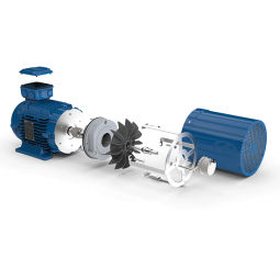
Product image:
Specification for DC equipment motor:
| Motor sort | Brush kind / Brushless kind / Stepper variety | ||
| Body measurement | 16mm ~ 130mm... can be tailored | ||
| Running velocity | Motor 1500-4000 rpm, Equipment Ratio 1/3 ~ 1/3000 | ||
| Output electrical power | 3W ~2200W... can be customized | ||
| Output shaft | round shaft, D-minimize shaft, crucial-way shaft, hollow shaft… | ||
| Voltage type | 12V / 24V / 36V / 48V / 90V / 110V /220V... can be customized | ||
| Add-ons | Internal driver / Exterior driver / Connector / Brake / Encoder… | ||
| Gearbox sort | Parallel shaft | ||
| Correct angle hollow worm shaft | Proper angle bevel hollow shaft | Flat variety hollow shaft | |
| Proper angle sound worm shaft | Correct angle bevel strong shaft | Flat variety solid shaft | |
| Planetary heart shaft | |||
FAQ
Q: Can you make the equipment motor with customization?
A: Yes, we can personalize for each your request, like electricity, voltage, speed, shaft dimensions, wires, connectors, IP grade, etc.
Q: Do you give samples?
A: Yes. Sample is offered for screening.
Q: What is your MOQ?
A: It is 10pcs for the commencing of our business.
Q: What's your lead time?
A: Standard solution want 5-30days, a little bit longer for personalized items.
Q: Do you give technological innovation help?
A: Yes. Our firm have layout and improvement team, we can supply technological innovation assist if you
need.
Q: How to ship to us?
A: It is accessible by air, or by sea, or by teach.
Q: How to pay out the money?
A: T/T and L/C is chosen, with various forex, such as USD, EUR, RMB, and so forth.
Q: How can I know the solution is suitable for me?
A: >1ST verify drawing and specification >2nd take a look at sample >3rd commence mass production.
Q: Can I come to your firm to pay a visit to?
A: Sure, you are welcome to pay a visit to us at any time.
Q: How shall we speak to you?
A: You can send inquiry directly, and we will respond within 24 several hours.
|
US $15-25 / Piece | |
1 Piece (Min. Order) |
###
| Application: | Industrial |
|---|---|
| Operating Speed: | Constant Speed |
| Excitation Mode: | Excited |
| Function: | Driving |
| Casing Protection: | Protection Type |
| Number of Poles: | 4 |
###
| Samples: |
US$ 50/Piece
1 Piece(Min.Order) |
|---|
###
| Customization: |
Available
|
|---|
###
| Motor type | Brush type / Brushless type / Stepper type | ||
| Frame size | 16mm ~ 130mm... can be customized | ||
| Running speed | Motor 1500-4000 rpm, Gear Ratio 1/3 ~ 1/3000 | ||
| Output power | 3W ~2200W... can be customized | ||
| Output shaft | round shaft, D-cut shaft, key-way shaft, hollow shaft… | ||
| Voltage type | 12V / 24V / 36V / 48V / 90V / 110V /220V... can be customized | ||
| Accessories | Internal driver / External driver / Connector / Brake / Encoder… | ||
| Gearbox type | Parallel shaft | ||
| Right angle hollow worm shaft | Right angle bevel hollow shaft | Flat type hollow shaft | |
| Right angle solid worm shaft | Right angle bevel solid shaft | Flat type solid shaft | |
| Planetary center shaft | |||
|
US $15-25 / Piece | |
1 Piece (Min. Order) |
###
| Application: | Industrial |
|---|---|
| Operating Speed: | Constant Speed |
| Excitation Mode: | Excited |
| Function: | Driving |
| Casing Protection: | Protection Type |
| Number of Poles: | 4 |
###
| Samples: |
US$ 50/Piece
1 Piece(Min.Order) |
|---|
###
| Customization: |
Available
|
|---|
###
| Motor type | Brush type / Brushless type / Stepper type | ||
| Frame size | 16mm ~ 130mm... can be customized | ||
| Running speed | Motor 1500-4000 rpm, Gear Ratio 1/3 ~ 1/3000 | ||
| Output power | 3W ~2200W... can be customized | ||
| Output shaft | round shaft, D-cut shaft, key-way shaft, hollow shaft… | ||
| Voltage type | 12V / 24V / 36V / 48V / 90V / 110V /220V... can be customized | ||
| Accessories | Internal driver / External driver / Connector / Brake / Encoder… | ||
| Gearbox type | Parallel shaft | ||
| Right angle hollow worm shaft | Right angle bevel hollow shaft | Flat type hollow shaft | |
| Right angle solid worm shaft | Right angle bevel solid shaft | Flat type solid shaft | |
| Planetary center shaft | |||
Benefits of a Planetary Motor
If you're looking for an affordable way to power a machine, consider purchasing a Planetary Motor. These units are designed to provide a massive range of gear reductions, and are capable of generating much higher torques and torque density than other types of drive systems. This article will explain why you should consider purchasing one for your needs. And we'll also discuss the differences between a planetary and spur gear system, as well as how you can benefit from them.
planetary gears
Planetary gears in a motor are used to reduce the speed of rotation of the armature 8. The reduction ratio is determined by the structure of the planetary gear device. The output shaft 5 rotates through the device with the assistance of the ring gear 4. The ring gear 4 engages with the pinion 3 once the shaft is rotated to the engagement position. The transmission of rotational torque from the ring gear to the armature causes the motor to start.
The axial end surface of a planetary gear device has two circular grooves 21. The depressed portion is used to retain lubricant. This lubricant prevents foreign particles from entering the planetary gear space. This feature enables the planetary gear device to be compact and lightweight. The cylindrical portion also minimizes the mass inertia. In this way, the planetary gear device can be a good choice for a motor with limited space.
Because of their compact footprint, planetary gears are great for reducing heat. In addition, this design allows them to be cooled. If you need high speeds and sustained performance, you may want to consider using lubricants. The lubricants present a cooling effect and reduce noise and vibration. If you want to maximize the efficiency of your motor, invest in a planetary gear hub drivetrain.
The planetary gear head has an internal sun gear that drives the multiple outer gears. These gears mesh together with the outer ring that is fixed to the motor housing. In industrial applications, planetary gears are used with an increasing number of teeth. This distribution of power ensures higher efficiency and transmittable torque. There are many advantages of using a planetary gear motor. These advantages include:
planetary gearboxes
A planetary gearbox is a type of drivetrain in which the input and output shafts are connected with a planetary structure. A planetary gearset can have three main components: an input gear, a planetary output gear, and a stationary position. Different gears can be used to change the transmission ratios. The planetary structure arrangement gives the planetary gearset high rigidity and minimizes backlash. This high rigidity is crucial for quick start-stop cycles and rotational direction.
Planetary gears need to be lubricated regularly to prevent wear and tear. In addition, transmissions must be serviced regularly, which can include fluid changes. The gears in a planetary gearbox will wear out with time, and any problems should be repaired immediately. However, if the gears are damaged, or if they are faulty, a planetary gearbox manufacturer will repair it for free.
A planetary gearbox is typically a 2-speed design, but professional manufacturers can provide triple and single-speed sets. Planetary gearboxes are also compatible with hydraulic, electromagnetic, and dynamic braking systems. The first step to designing a planetary gearbox is defining your application and the desired outcome. Famous constructors use a consultative modeling approach, starting each project by studying machine torque and operating conditions.
As the planetary gearbox is a compact design, space is limited. Therefore, bearings need to be selected carefully. The compact needle roller bearings are the most common option, but they cannot tolerate large axial forces. Those that can handle high axial forces, such as worm gears, should opt for tapered roller bearings. So, what are the advantages and disadvantages of a helical gearbox?
planetary gear motors
When we think of planetary gear motors, we tend to think of large and powerful machines, but in fact, there are many smaller, more inexpensive versions of the same machine. These motors are often made of plastic, and can be as small as six millimeters in diameter. Unlike their larger counterparts, they have only one gear in the transmission, and are made with a small diameter and small number of teeth.
They are similar to the solar system, with the planets rotating around a sun gear. The planet pinions mesh with the ring gear inside the sun gear. All of these gears are connected by a planetary carrier, which is the output shaft of the gearbox. The ring gear and planetary carrier assembly are attached to each other through a series of joints. When power is applied to any of these members, the entire assembly will rotate.
Compared to other configurations, planetary gearmotors are more complicated. Their construction consists of a sun gear centered in the center and several smaller gears that mesh with the central sun gear. These gears are enclosed in a larger internal tooth gear. This design allows them to handle larger loads than conventional gear motors, as the load is distributed among several gears. This type of motor is typically more expensive than other configurations, but can withstand the higher-load requirements of some machines.
Because they are cylindrical in shape, planetary gear motors are incredibly versatile. They can be used in various applications, including automatic transmissions. They are also used in applications where high-precision and speed are necessary. Furthermore, the planetary gear motor is robust and is characterized by low vibrations. The advantages of using a planetary gear motor are vast and include:
planetary gears vs spur gears
A planetary motor uses multiple teeth to share the load of rotating parts. This gives planetary gears high stiffness and low backlash - often as low as one or two arc minutes. These characteristics are important for applications that undergo frequent start-stop cycles or rotational direction changes. This article discusses the benefits of planetary gears and how they differ from spur gears. You can watch the animation below for a clearer understanding of how they operate and how they differ from spur gears.
Planetary gears move in a periodic manner, with a relatively small meshing frequency. As the meshing frequency increases, the amplitude of the frequency also increases. The amplitude of this frequency is small at low clearance values, and increases dramatically at higher clearance levels. The amplitude of the frequency is higher when the clearance reaches 0.2-0.6. The amplitude increases rapidly, whereas wear increases slowly after the initial 0.2-0.6-inch-wide clearance.
In high-speed, high-torque applications, a planetary motor is more effective. It has multiple contact points for greater torque and higher speed. If you are not sure which type to choose, you can consult with an expert and design a custom gear. If you are unsure of what type of motor you need, contact Twirl Motor and ask for help choosing the right one for your application.
A planetary gear arrangement offers a number of advantages over traditional fixed-axis gear system designs. The compact size allows for lower loss of effectiveness, and the more planets in the gear system enhances the torque density and capacity. Another benefit of a planetary gear system is that it is much stronger and more durable than its spur-gear counterpart. Combined with its many advantages, a planetary gear arrangement offers a superior solution to your shifting needs.
planetary gearboxes as a compact alternative to pinion-and-gear reducers
While traditional pinion-and-gear reducer design is bulky and complex, planetary gearboxes are compact and flexible. They are suitable for many applications, especially where space and weight are issues, as well as torque and speed reduction. However, understanding their mechanism and working isn't as simple as it sounds, so here are some of the key benefits of planetary gearing.
Planetary gearboxes work by using two planetary gears that rotate around their own axes. The sun gear is used as the input, while the planetary gears are connected via a casing. The ratio of these gears is -Ns/Np, with 24 teeth in the sun gear and -3/2 on the planet gear.
Unlike traditional pinion-and-gear reducer designs, planetary gearboxes are much smaller and less expensive. A planetary gearbox is about 50% smaller and weighs less than a pinion-and-gear reducer. The smaller gear floats on top of three large gears, minimizing the effects of vibration and ensuring consistent transmission over time.
Planetary gearboxes are a good alternative to pinion-and-gear drive systems because they are smaller, less complex and offer a higher reduction ratio. Their meshing arrangement is similar to the Milky Way, with the sun gear in the middle and two or more outer gears. They are connected by a carrier that sets their spacing and incorporates an output shaft.
Compared to pinion-and-gear reduces, planetary gearboxes offer higher speed reduction and torque capacity. As a result, planetary gearboxes are small and compact and are often preferred for space-constrained applications. But what about the high torque transfer? If you're looking for a compact alt
editor by czh 2023-01-12