Product Description
Product specifications
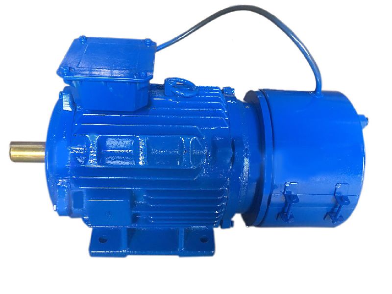
The following are the specifications that our company's Micro AC gear motors 140w can achieved. You can also contact us to tell us the power, voltage, torque and other parameters you need. We can accept and customize. and You can also contact us for drawings and detailed parameters.
| Band name | Lunyee |
| Out Power | 140w |
| Dimension | 90mm |
| Voltage | 380v |
| Frequency | 50Hz 60Hz |
| Phase | Three phase |
| Current | 1.251 A |
| Rated speed | 1350/1680 r/min |
| Starting torque | 1.353/1.684 N.M |
| Rated torqur | 0.796/0.990N.M |
| Rated time | Continuous |
| Motor Shaft type | Pinion shaft Round shaft Keyway |
| Accessories that can be added | gear box Terminal box w/fan w/ forced fan eleceromagnetic brake thermally |
| Micro ac gear motor type | Induction motor Reversible motor Torque motor Speed control motor Right angle gear motor Brake motor |
Product Features:
High efficiency
High torque Low speed
Low noise Long life Strong reliability
Running smoothly
Brushless environmental protection
Simple structure easy to use
Factory supplier best price
Suitable for extreme environments
Wide range of applications
product details
1.AC Gear Motor
Compact structure, good sealing performance, low noise, long life,low operating temperature Adjustable speed, reversible, CHINAMFG and reverse
2.All Copper Coil
All copper coil, fast heat dissipation, life is 10 times that of ordinary coil
3.High precision hard tooth surface
The gear has high precision, high hardness, anti-rust treatment, waterproof and quiet, long life
Application
AC gear motor widely used in Industrial equipment, machine tools, agricultural appliances, commercial office, medical equipment, household appliances, aviation and other fields. Such as treadmill, sewing machine, meat grinder , tortilla press maker, Apparel Machine, Textile Machine, Metal Coating Machinery, Pumps, Sprayers, heavy mine equipment, Packing Machine, nebulizer, table fan, Face Mask Machine, Rehabilitation Therapy Supplies, refrigerator, Air Purifiers, Fermenting Equipment. and many more.
Company Certifaction
About us:
ZheJiang CHINAMFG Industries Co., Limited. company, is the recognized top manufacturer of industrial humidification system inChina. Our factory has 3 large workshops, covering 3,000 square meter area. We have more than 100 employees, equip with professional R&D team, reliable workers and efficient sales service team. Green focus on research and development, manufacture, and sale of humidifying, air cooling, dedusting, dehumidifying and energy saving equipment. Our company is evolving as the change of customers' needs, we are committed to developing and engineering new technology to best suit our customers' demands. So far, we have got many patents on highly advanced and efficient humidifier designs.Working with Green, you will enjoy the latest and most advanced technology and kindest service.
Our Mine Product:
DC/AC motor, stepper motor, gearbox, CNC engraving machine, industrial humidifier.
Our Services:
Each of our products will undergo rigorous testing before leaving the factory. We will provide you with professional designs and solutions, high-quality products and high-quality services according to your needs. If you have any questions, please feel free to
contact us. We will serve you immediately.
Packing &Shipping
Inside : Plastic bags with Chemical Desiccant For Gear Housing
Middle : Individual Carton packaging Outside : Wooden Box
Shipment: TNT, DHL, UPS, FedEx,EMS etc.Or use the shipment your specified.
Strict product packaging ensures that the product is not damaged during transportation.
FAQ
Q1 Are you a manufacturer or a trading company?
We are a motor in China.
Q2 What's your warranty?
One-year.
Q3 Can you give more discounts if more quantity and how many?
We can afford discounts and rate based on updated quantity.
Q4 Can you make OEM/ODM order?
Yes, we have rich experience on OEM/ODM order.
Q5 Delivery
Sample can be afforded within 5-7days and volume order can be finished within 15-20days.
Q6 About sample?
Available.
Q7 Which of payments you support?
T/T, L/C,PAYPAL, CREDIT CARD.
Q8 Which of transportations you support?
Sea, Air cargo, Train, DHL/FEDEX/UPS/TNT.
Q9 What you can do if we still have worry on your product?
We can afford sample for testing, if approval then negotiate cooperation later.
/* January 22, 2571 19:08:37 */!function(){function s(e,r){var a,o={};try{e&&e.split(",").forEach(function(e,t){e&&(a=e.match(/(.*?):(.*)$/))&&1
| Application: | Industrial |
|---|---|
| Speed: | Variable Speed |
| Number of Stator: | Three-Phase |
| Function: | Driving, Control |
| Casing Protection: | Closed Type |
| Number of Poles: | 4 |
| Samples: |
US$ 10/Piece
1 Piece(Min.Order) | |
|---|
| Customization: |
Available
|
|
|---|
How do brake motors impact the overall productivity of manufacturing processes?
Brake motors have a significant impact on the overall productivity of manufacturing processes by enhancing operational efficiency, improving safety, and enabling precise control over motion. They play a crucial role in ensuring smooth and controlled movement, which is vital for the seamless operation of machinery and equipment. Here's a detailed explanation of how brake motors impact the overall productivity of manufacturing processes:
- Precise Control and Positioning: Brake motors enable precise control over the speed, acceleration, and deceleration of machinery and equipment. This precise control allows for accurate positioning, alignment, and synchronization of various components, resulting in improved product quality and reduced errors. The ability to precisely control the motion enhances the overall productivity of manufacturing processes by minimizing waste, rework, and downtime.
- Quick Deceleration and Stopping: Brake motors provide fast and controlled deceleration and stopping capabilities. This is particularly important in manufacturing processes that require frequent changes in speed or direction. The ability to rapidly decelerate and stop equipment allows for efficient handling of workpieces, quick tool changes, and seamless transitions between manufacturing steps. It reduces cycle times and improves overall productivity by minimizing unnecessary delays and optimizing throughput.
- Improved Safety: Brake motors enhance safety in manufacturing processes by providing reliable braking functionality. They help prevent coasting or unintended movement of equipment when power is cut off or during emergency situations. The braking capability of brake motors contributes to the safe operation of machinery, protects personnel, and prevents damage to equipment or workpieces. By ensuring a safe working environment, brake motors help maintain uninterrupted production and minimize the risk of accidents or injuries.
- Enhanced Equipment Performance: The integration of brake motors into manufacturing equipment improves overall performance. Brake motors work in conjunction with motor control devices, such as variable frequency drives (VFDs) or servo systems, to optimize motor operation. This integration allows for efficient power utilization, reduced energy consumption, and improved responsiveness. By maximizing equipment performance, brake motors contribute to higher productivity, lower operational costs, and increased output.
- Reduced Downtime and Maintenance: Brake motors are designed for durability and reliability, reducing the need for frequent maintenance and minimizing downtime. The robust construction and high-quality components of brake motors ensure long service life and consistent performance. This reliability translates into fewer unplanned shutdowns, reduced maintenance requirements, and improved overall equipment availability. By minimizing downtime and maintenance-related interruptions, brake motors contribute to increased productivity and manufacturing efficiency.
- Flexibility and Adaptability: Brake motors offer flexibility and adaptability in manufacturing processes. They can be integrated into various types of machinery and equipment, spanning different industries and applications. Brake motors can be customized to meet specific requirements, such as adjusting brake torque or incorporating specific control algorithms. This adaptability allows manufacturers to optimize their processes, accommodate changing production needs, and increase overall productivity.
In summary, brake motors impact the overall productivity of manufacturing processes by providing precise control and positioning, enabling quick deceleration and stopping, improving safety, enhancing equipment performance, reducing downtime and maintenance, and offering flexibility and adaptability. Their role in ensuring smooth and controlled movement, combined with their reliable braking functionality, contributes to efficient and seamless manufacturing operations, ultimately leading to increased productivity, improved product quality, and cost savings.
How does a brake motor enhance safety in industrial and manufacturing settings?
In industrial and manufacturing settings, brake motors play a crucial role in enhancing safety by providing reliable braking and control mechanisms. These motors are specifically designed to address safety concerns and mitigate potential risks associated with rotating machinery and equipment. Here's a detailed explanation of how brake motors enhance safety in industrial and manufacturing settings:
1. Controlled Stopping: Brake motors offer controlled stopping capabilities, allowing for precise and predictable deceleration of rotating machinery. This controlled stopping helps prevent abrupt stops or sudden changes in motion, reducing the risk of accidents, equipment damage, and injury to personnel. By providing smooth and controlled stopping, brake motors enhance safety during machine shutdowns, emergency stops, or power loss situations.
2. Emergency Stop Functionality: Brake motors often incorporate emergency stop functionality as a safety feature. In case of an emergency or hazardous situation, operators can activate the emergency stop function to immediately halt the motor and associated machinery. This rapid and reliable stopping capability helps prevent accidents, injuries, and damage to equipment, providing an essential safety measure in industrial environments.
3. Load Holding Capability: Brake motors have the ability to hold loads in position when the motor is not actively rotating. This load holding capability is particularly important for applications where the load needs to be securely held in place, such as vertical lifting mechanisms or inclined conveyors. By preventing unintended movement or drift of the load, brake motors ensure safe operation and minimize the risk of uncontrolled motion that could lead to accidents or damage.
4. Overload Protection: Brake motors often incorporate overload protection mechanisms to safeguard against excessive loads. These protection features can include thermal overload protection, current limiters, or torque limiters. By detecting and responding to overload conditions, brake motors help prevent motor overheating, component failure, and potential hazards caused by overburdened machinery. This protection enhances the safety of personnel and prevents damage to equipment.
5. Failsafe Braking: Brake motors are designed with failsafe braking systems that ensure reliable braking even in the event of power loss or motor failure. These systems can use spring-loaded brakes or electromagnetic brakes that engage automatically when power is cut off or when a fault is detected. Failsafe braking prevents uncontrolled motion and maintains the position of rotating machinery, reducing the risk of accidents, injury, or damage during power interruptions or motor failures.
6. Integration with Safety Systems: Brake motors can be integrated into safety systems and control architectures to enhance overall safety in industrial settings. They can be connected to safety relays, programmable logic controllers (PLCs), or safety-rated drives to enable advanced safety functionalities such as safe torque off (STO) or safe braking control. This integration ensures that the brake motor operates in compliance with safety standards and facilitates coordinated safety measures across the machinery or production line.
7. Compliance with Safety Standards: Brake motors are designed and manufactured in compliance with industry-specific safety standards and regulations. These standards, such as ISO standards or Machinery Directive requirements, define the safety criteria and performance expectations for rotating machinery. By using brake motors that meet these safety standards, industrial and manufacturing settings can ensure a higher level of safety, regulatory compliance, and risk mitigation.
8. Operator Safety: Brake motors also contribute to operator safety by reducing the risk of unintended movement or hazardous conditions. The controlled stopping and load holding capabilities of brake motors minimize the likelihood of unexpected machine behavior that could endanger operators. Additionally, the incorporation of safety features like emergency stop buttons or remote control options provides operators with convenient means to stop or control the machinery from a safe distance, reducing their exposure to potential hazards.
By providing controlled stopping, emergency stop functionality, load holding capability, overload protection, failsafe braking, integration with safety systems, compliance with safety standards, and operator safety enhancements, brake motors significantly enhance safety in industrial and manufacturing settings. These motors play a critical role in preventing accidents, injuries, and equipment damage, contributing to a safer working environment and ensuring the well-being of personnel.
What is a brake motor and how does it operate?
A brake motor is a type of electric motor that incorporates a mechanical braking system. It is designed to provide both motor power and braking functionality in a single unit. The brake motor is commonly used in applications where rapid and precise stopping or holding of loads is required. Here's a detailed explanation of what a brake motor is and how it operates:
A brake motor consists of two main components: the electric motor itself and a braking mechanism. The electric motor converts electrical energy into mechanical energy to drive a load. The braking mechanism, usually located at the non-drive end of the motor, provides the necessary braking force to stop or hold the load when the motor is turned off or power is cut off.
The braking mechanism in a brake motor typically employs one of the following types of brakes:
- Electromagnetic Brake: An electromagnetic brake is the most common type used in brake motors. It consists of an electromagnetic coil and a brake shoe or armature. When the motor is powered, the electromagnetic coil is energized, creating a magnetic field that attracts the brake shoe or armature. This releases the brake and allows the motor to rotate and drive the load. When the power is cut off or the motor is turned off, the electromagnetic coil is de-energized, and the brake shoe or armature is pressed against a stationary surface, creating friction and stopping the motor's rotation.
- Mechanical Brake: Some brake motors use mechanical brakes, such as disc brakes or drum brakes. These brakes employ friction surfaces, such as brake pads or brake shoes, which are pressed against a rotating disc or drum attached to the motor shaft. When the motor is powered, the brake is disengaged, allowing the motor to rotate. When the power is cut off or the motor is turned off, a mechanical mechanism, such as a spring or a cam, engages the brake, creating friction and stopping the motor's rotation.
The operation of a brake motor involves the following steps:
- Motor Operation: When power is supplied to the brake motor, the electric motor converts electrical energy into mechanical energy, which is used to drive the load. The brake is disengaged, allowing the motor shaft to rotate freely.
- Stopping or Holding: When the power is cut off or the motor is turned off, the braking mechanism is engaged. In the case of an electromagnetic brake, the electromagnetic coil is de-energized, and the brake shoe or armature is pressed against a stationary surface, creating friction and stopping the motor's rotation. In the case of a mechanical brake, a mechanical mechanism engages the brake pads or shoes against a rotating disc or drum, creating friction and stopping the motor's rotation.
- Release and Restart: To restart the motor, power is supplied again, and the braking mechanism is disengaged. In the case of an electromagnetic brake, the electromagnetic coil is energized, releasing the brake shoe or armature. In the case of a mechanical brake, the mechanical mechanism disengages the brake pads or shoes from the rotating disc or drum.
Brake motors are commonly used in applications that require precise stopping or holding of loads, such as cranes, hoists, conveyors, machine tools, and elevators. The incorporation of a braking system within the motor eliminates the need for external braking devices or additional components, simplifying the design and installation process. Brake motors enhance safety, efficiency, and control in industrial applications by providing reliable and rapid braking capabilities.


editor by CX 2024-04-23
China Custom Low Rpm Mini AC Electric Motor with Brake and Gearbox 120W supplier
Product Description
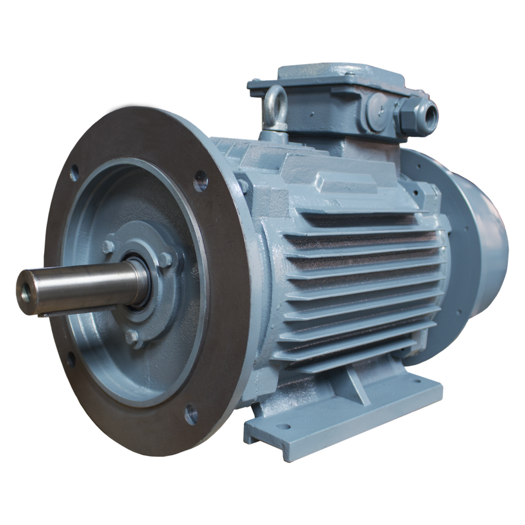
A. Specification of Low RPM Mini AC Electric Motor with Brake and Gearbox 120W:
1. Voltage: 110/220V
2. Speed: 2-600RPM
3. Torque: 18.4-200Kgf.cm
4. Output Power: 120W
5. Gearbox Ratio: 1:3 to 1: 750
6. Gearbox Diameter: 90mm
7. Gearbox Length: 65mm
8. Motor Length: 141mm
9. Shaft Diameter: 15mm
10. Motor Weight: 3.8Kg
11. Gearbox Weight: 1.21-1.45Kg
Note: The data sheet is only for reference, We can make the motor according to your requirement after Evaluation
B. Company Capacity
HangZhou CHINAMFG Motor Co. Ltd is a manufacturer and exporter of various of motors with over 10 years experience.
Our product ranges include:
1) DC Brush motor: 6-130mm diameter, 0.01-1000W output power
2) DC Spur Gear Motor: 12-110mm diameter, 0.1-300W output power
3) DC Planeary Gear Motor: 10-82mm diameter, 0.1-100W output power
4) Brushless DC Motor: 28-110mm, 5-1500W output power
5) Stepper Motor: NEMA 08 to NEMA 43, Can with gearbox and lead screw
6) Servo Motor: 42mm to 130mm diameter, 50-4000w
7) AC Gear Motor: 49 to 100mm diameter, 6-140 output power
1. Production Line:
2. Testing Equipment:
3. Certificates:
4. Customer Visits:
6. FAQ:
Q: What's your main products?
A:We currently produce Brushed Dc Motors, Brushed Dc gear Motors, Planetary Dc Gear Motors, Brushless Dc Motors, Stepper motors and Ac Motors etc. You can check the specifications for above motors on our website and you can email us to recommend needed motors per your specification too.
Q:How to select a suitable motor?
A:If you have motor pictures or drawings to show us, or you have detailed specs like voltage, speed, torque, motor size, working mode of the motor, needed life time and noise level etc, please do not hesitate to let us know, then we can recommend suitable motor per your request accordingly.
Q: Do you have customized service for your standard motors?
A:Yes, we can customize per your request for the voltage, speed, torque and shaft size/shape. If you need additional wires/cables soldered on the terminal or need to add connectors, or capacitors or EMC we can make it too.
Q:Do you have individual design service for motors?
A:Yes, we would like to design motors individually for our customers, but it may need some mould charge and design charge.
Q:Can I have samples for testing first?
A:Yes, definitely you can. After confirmed the needed motor specs, we will quote and provide a proforma invoice for samples, once we get the payment, we will get a PASS from our account department to proceed samples accordingly.
Q:How do you make sure motor quality?
A:We have our own inspection procedures: for incoming materials, we have signed sample and drawing to make sure qualified incoming materials; for production process, we have tour inspection in the process and final inspection to make sure qualified products before shipping.
Q:What's your lead time?
A:Generally speaking, our regular standard product will need 25-30days, a bit longer for customized products. But we are very flexible on the lead time, it will depends on the specific orders
Q:What's your payment term?
A:For all our new customers, we will need 40% deposite, 60% paid before shipment.
Q:When will you reply after got my inquiries?
A:We will response within 24 hours once get your inquires.
Q:How can I trust you to make sure my money is safe?
A:We are certified by the third party SGS and we have exported to over 85 countries up to June.2017. You can check our reputation with our current customers in your country (if our customers do not mind), or you can order via alibaba to get trade assurance from alibaba to make sure your money is safe.
Q:What's the minimum order quantity?
A:Our minimum order quantity depends on different motor models, please email us to check. Also, we usually do not accept personal use motor orders.
Q:What's your shipping method for motors?
A:For samples and packages less than 100kg, we usually suggest express shipping; For heavy packages, we usually suggest air shipping or sea shipping. But it all depends on our customers' needs.
Q:What certifications do you have?
A:We currently have CE and ROSH certifications.
Q:Can you send me your price list?
A:Since we have hundreds of different products, and price varies per different specifications, we are not able to offer a price list. But we can quote within 24 hours once got your inquirues to make sure you can get the price in time.
Q:Can I visit your company?
A:Yes, welcome to visit our company, but please let us know at least 2 weeks in advance to help us make sure no other meetings during the day you visit us. Thanks!
Weclome contact with us if have any questions about this motor or other products!
| Application: | Universal, Household Appliances, Power Tools, Others |
|---|---|
| Operating Speed: | Low Speed |
| Function: | Driving |
| Casing Protection: | Closed Type |
| Structure and Working Principle: | Brush |
| Type: | AC Gear Motor |
| Samples: |
US$ 120/Piece
1 Piece(Min.Order) | |
|---|
| Customization: |
Available
|
|
|---|
How do brake motors handle variations in brake torque and response time?
Brake motors are designed to handle variations in brake torque and response time to ensure reliable and efficient braking performance. These variations can arise due to different operating conditions, load characteristics, or specific application requirements. Here's a detailed explanation of how brake motors handle variations in brake torque and response time:
- Brake Design and Construction: The design and construction of brake systems in brake motors play a crucial role in handling variations in brake torque and response time. Brake systems typically consist of brake pads or shoes that press against a brake disc or drum to generate frictional forces and provide braking action. The materials used for the brake components, such as brake linings, can be selected or designed to offer a wide range of torque capacities and response characteristics. By choosing the appropriate materials and optimizing the brake system design, brake motors can accommodate variations in torque requirements and response times.
- Brake Control Mechanisms: Brake motors employ different control mechanisms to manage brake torque and response time. These mechanisms can be mechanical, electrical, or a combination of both. Mechanical control mechanisms often utilize springs or levers to apply and release the brake, while electrical control mechanisms rely on electromagnets or solenoids to engage or disengage the brake. The control mechanisms can be adjusted or configured to modulate the brake torque and response time based on the specific needs of the application.
- Brake Torque Adjustments: Brake motors may offer provisions for adjusting the brake torque to accommodate variations in load requirements. This can be achieved through the selection of different brake linings or by adjusting the spring tension or magnetic force within the brake system. By modifying the brake torque, brake motors can provide the necessary braking force to meet the demands of different operating conditions or load characteristics.
- Response Time Optimization: Brake motors can be engineered to optimize the response time of the braking system. The response time refers to the time it takes for the brake to engage or disengage once the control signal is applied. Several factors can influence the response time, including the design of the control mechanism, the characteristics of the brake linings, and the braking system's overall dynamics. By fine-tuning these factors, brake motors can achieve faster or slower response times as required by the application, ensuring effective and timely braking action.
- Electronic Control Systems: In modern brake motors, electronic control systems are often employed to enhance the flexibility and precision of brake torque and response time adjustments. These systems utilize sensors, feedback mechanisms, and advanced control algorithms to monitor and regulate the brake performance. Electronic control allows for real-time adjustments and precise control of the brake torque and response time, making brake motors more adaptable to variations in operating conditions and load requirements.
By combining appropriate brake design and construction, control mechanisms, torque adjustments, response time optimization, and electronic control systems, brake motors can effectively handle variations in brake torque and response time. This enables them to provide reliable and efficient braking performance across a wide range of operating conditions, load characteristics, and application requirements.
How does a brake motor enhance safety in industrial and manufacturing settings?
In industrial and manufacturing settings, brake motors play a crucial role in enhancing safety by providing reliable braking and control mechanisms. These motors are specifically designed to address safety concerns and mitigate potential risks associated with rotating machinery and equipment. Here's a detailed explanation of how brake motors enhance safety in industrial and manufacturing settings:
1. Controlled Stopping: Brake motors offer controlled stopping capabilities, allowing for precise and predictable deceleration of rotating machinery. This controlled stopping helps prevent abrupt stops or sudden changes in motion, reducing the risk of accidents, equipment damage, and injury to personnel. By providing smooth and controlled stopping, brake motors enhance safety during machine shutdowns, emergency stops, or power loss situations.
2. Emergency Stop Functionality: Brake motors often incorporate emergency stop functionality as a safety feature. In case of an emergency or hazardous situation, operators can activate the emergency stop function to immediately halt the motor and associated machinery. This rapid and reliable stopping capability helps prevent accidents, injuries, and damage to equipment, providing an essential safety measure in industrial environments.
3. Load Holding Capability: Brake motors have the ability to hold loads in position when the motor is not actively rotating. This load holding capability is particularly important for applications where the load needs to be securely held in place, such as vertical lifting mechanisms or inclined conveyors. By preventing unintended movement or drift of the load, brake motors ensure safe operation and minimize the risk of uncontrolled motion that could lead to accidents or damage.
4. Overload Protection: Brake motors often incorporate overload protection mechanisms to safeguard against excessive loads. These protection features can include thermal overload protection, current limiters, or torque limiters. By detecting and responding to overload conditions, brake motors help prevent motor overheating, component failure, and potential hazards caused by overburdened machinery. This protection enhances the safety of personnel and prevents damage to equipment.
5. Failsafe Braking: Brake motors are designed with failsafe braking systems that ensure reliable braking even in the event of power loss or motor failure. These systems can use spring-loaded brakes or electromagnetic brakes that engage automatically when power is cut off or when a fault is detected. Failsafe braking prevents uncontrolled motion and maintains the position of rotating machinery, reducing the risk of accidents, injury, or damage during power interruptions or motor failures.
6. Integration with Safety Systems: Brake motors can be integrated into safety systems and control architectures to enhance overall safety in industrial settings. They can be connected to safety relays, programmable logic controllers (PLCs), or safety-rated drives to enable advanced safety functionalities such as safe torque off (STO) or safe braking control. This integration ensures that the brake motor operates in compliance with safety standards and facilitates coordinated safety measures across the machinery or production line.
7. Compliance with Safety Standards: Brake motors are designed and manufactured in compliance with industry-specific safety standards and regulations. These standards, such as ISO standards or Machinery Directive requirements, define the safety criteria and performance expectations for rotating machinery. By using brake motors that meet these safety standards, industrial and manufacturing settings can ensure a higher level of safety, regulatory compliance, and risk mitigation.
8. Operator Safety: Brake motors also contribute to operator safety by reducing the risk of unintended movement or hazardous conditions. The controlled stopping and load holding capabilities of brake motors minimize the likelihood of unexpected machine behavior that could endanger operators. Additionally, the incorporation of safety features like emergency stop buttons or remote control options provides operators with convenient means to stop or control the machinery from a safe distance, reducing their exposure to potential hazards.
By providing controlled stopping, emergency stop functionality, load holding capability, overload protection, failsafe braking, integration with safety systems, compliance with safety standards, and operator safety enhancements, brake motors significantly enhance safety in industrial and manufacturing settings. These motors play a critical role in preventing accidents, injuries, and equipment damage, contributing to a safer working environment and ensuring the well-being of personnel.
What is a brake motor and how does it operate?
A brake motor is a type of electric motor that incorporates a mechanical braking system. It is designed to provide both motor power and braking functionality in a single unit. The brake motor is commonly used in applications where rapid and precise stopping or holding of loads is required. Here's a detailed explanation of what a brake motor is and how it operates:
A brake motor consists of two main components: the electric motor itself and a braking mechanism. The electric motor converts electrical energy into mechanical energy to drive a load. The braking mechanism, usually located at the non-drive end of the motor, provides the necessary braking force to stop or hold the load when the motor is turned off or power is cut off.
The braking mechanism in a brake motor typically employs one of the following types of brakes:
- Electromagnetic Brake: An electromagnetic brake is the most common type used in brake motors. It consists of an electromagnetic coil and a brake shoe or armature. When the motor is powered, the electromagnetic coil is energized, creating a magnetic field that attracts the brake shoe or armature. This releases the brake and allows the motor to rotate and drive the load. When the power is cut off or the motor is turned off, the electromagnetic coil is de-energized, and the brake shoe or armature is pressed against a stationary surface, creating friction and stopping the motor's rotation.
- Mechanical Brake: Some brake motors use mechanical brakes, such as disc brakes or drum brakes. These brakes employ friction surfaces, such as brake pads or brake shoes, which are pressed against a rotating disc or drum attached to the motor shaft. When the motor is powered, the brake is disengaged, allowing the motor to rotate. When the power is cut off or the motor is turned off, a mechanical mechanism, such as a spring or a cam, engages the brake, creating friction and stopping the motor's rotation.
The operation of a brake motor involves the following steps:
- Motor Operation: When power is supplied to the brake motor, the electric motor converts electrical energy into mechanical energy, which is used to drive the load. The brake is disengaged, allowing the motor shaft to rotate freely.
- Stopping or Holding: When the power is cut off or the motor is turned off, the braking mechanism is engaged. In the case of an electromagnetic brake, the electromagnetic coil is de-energized, and the brake shoe or armature is pressed against a stationary surface, creating friction and stopping the motor's rotation. In the case of a mechanical brake, a mechanical mechanism engages the brake pads or shoes against a rotating disc or drum, creating friction and stopping the motor's rotation.
- Release and Restart: To restart the motor, power is supplied again, and the braking mechanism is disengaged. In the case of an electromagnetic brake, the electromagnetic coil is energized, releasing the brake shoe or armature. In the case of a mechanical brake, the mechanical mechanism disengages the brake pads or shoes from the rotating disc or drum.
Brake motors are commonly used in applications that require precise stopping or holding of loads, such as cranes, hoists, conveyors, machine tools, and elevators. The incorporation of a braking system within the motor eliminates the need for external braking devices or additional components, simplifying the design and installation process. Brake motors enhance safety, efficiency, and control in industrial applications by providing reliable and rapid braking capabilities.
editor by CX 2023-10-23
China Best Sales Planetary Gearbox 12V Electric DC Gear Motor High Torque Low Rpm Motors for Robots dc motor
Product Description
| 24ZYJ DC Worm Gear Motor | |||||
| Basic Info | |||||
| Item | Data | ||||
| Tem Rise | 40K | ||||
| Working Tem | (-20ºC~+80ºC) | ||||
| Insulation Resistance | 100MΩ min 500VDC | ||||
| Surge Test | 500VAC for 1min | ||||
| Insulation Class | E | ||||
| Weight | 120g | ||||
The specification of DC Electrical Worm Gear Reducer Motor with high torque
| Specification | |||||||||||
| PN | Rated Voltage | Initial Speed | Ratio | Power | Noload Speed | Noload Current | Rated Speed | Rated Current | Rated Torque | Stall Torque | Stall Current |
| V DC | rpm | 1:xxx | W | rpm | mA | rpm | mA | Kg.cm | Kg.cm | mA | |
| 24ZYJ4632-65A | 12 | 6500 | 100 | 3 | 65 | 80 | 50 | 200 | 0.75 | 2 | 1000 |
| 24ZYJ4632-28A | 12 | 5000 | 180 | 3 | 28 | 80 | 23 | 200 | 1.6 | 3 | 1000 |
| 24ZYJ4632-38A | 12 | 9500 | 250 | 3 | 38 | 100 | 33 | 250 | 2.6 | 5 | 1500 |
The drawing of DC Electrical Worm Gear Reducer Motor with high torque
Below are only some typical models, for more specification or a customed motor, pls contact us.
About our company
Probond motors designs brush, brushless, stepper, hysteresis and linear motors to meet customers requirements.
Our motors use standard and special components with customer selected torque/speed requirements that can be modified to your applications.
The AC/DC gear motors are based upon to distinct magetic circuits that optimize motor design for high speed low torque and low speed high torque.
These motors give you lower rotational losses, excellent thermal transfer, interchangeable end caps, easily sealed. Options include connectors, encoders, shaft modifications, dimensional changes, etc.
Probond motor owns professional sales team and engineer team with more than 10 years experience in motor industry, based on China mainland handling overseas business for years, we know your needs better than others.
Probond Sonicare Toothbrush Motor and Thermostatic Valve Hysteresis Motor are our hot products on sell in 2017 with highly quality level and competitive price.
Please kindly contact us to get a catalogue.
Terms of Trade
| Terms of price | FOB,CIF,CFR,EXW,DDP,etc. |
| Terms of payment | 100% T/T in advance for samples |
| Bulk quantity payment way can be negotited | |
| Warranty | 12 months limited warranty once the items are delivered to the buyer. |
| Lead time | Usually within 2 weeks for trial orders, within 3 weeks for bulk orders. |
| Package | Carton o plywood pallet. |
| Place of loading | ZheJiang , HangZhou, etc. |
| Shipment carrier | Items are usually shipped via Fedex,DHL, TNT,UPS,EMS for trial orders and via vessel for bulk orders. |
| Delivery time | Usually within 5 working days by Express 15-30 working days by vessel |
Our promise to our Customers:
1. Answer customer's inquiry within 2 working days.
2. Reply to our customer questions & Concerns within 3 working days.
3. Acknowledge Customer purchase orders within 24 hours.
| Application: | Universal, Industrial, Household Appliances, Car, Power Tools, Beauty Equipments |
|---|---|
| Operating Speed: | High Speed |
| Excitation Mode: | Excited |
| Function: | Control, Driving |
| Casing Protection: | Open Type |
| Number of Poles: | 6 |
| Samples: |
US$ 10/Piece
1 Piece(Min.Order) | |
|---|
| Customization: |
Available
| Customized Request |
|---|

What Is a Gear Motor?
A gear motor is an electric motor coupled with a gear train. It uses either DC or AC power to achieve its purpose. The primary benefit of a gear reducer is its ability to multiply torque while maintaining a compact size. The trade-off of this additional torque comes in the form of a reduced output shaft speed and overall efficiency. However, proper gear technology and ratios provide optimum output and speed profiles. This type of motor unlocks the full potential of OEM equipment.
Inertial load
Inertial load on a gear motor is the amount of force a rotating device produces due to its inverse square relationship with its inertia. The greater the inertia, the less torque can be produced by the gear motor. However, if the inertia is too high, it can cause problems with positioning, settling time, and controlling torque and velocity. Gear ratios should be selected for optimal power transfer.
The duration of acceleration and braking time of a gear motor depends on the type of driven load. An inertia load requires longer acceleration time whereas a friction load requires breakaway torque to start the load and maintain it at its desired speed. Too short a time period can cause excessive gear loading and may result in damaged gears. A safe approach is to disconnect the load when power is disconnected to prevent inertia from driving back through the output shaft.
Inertia is a fundamental concept in the design of motors and drive systems. The ratio of mass and inertia of a load to a motor determines how well the motor can control its speed during acceleration or deceleration. The mass moment of inertia, also called rotational inertia, is dependent on the mass, geometry, and center of mass of an object.
Applications
There are many applications of gear motors. They provide a powerful yet efficient means of speed and torque control. They can be either AC or DC, and the two most common motor types are the three-phase asynchronous and the permanent magnet synchronous servomotor. The type of motor used for a given application will determine its cost, reliability, and complexity. Gear motors are typically used in applications where high torque is required and space or power constraints are significant.
There are two types of gear motors. Depending on the ratio, each gear has an output shaft and an input shaft. Gear motors use hydraulic pressure to produce torque. The pressure builds on one side of the motor until it generates enough torque to power a rotating load. This type of motors is not recommended for applications where load reversals occur, as the holding torque will diminish with age and shaft vibration. However, it can be used for precision applications.
The market landscape shows the competitive environment of the gear motor industry. This report also highlights key items, income and value creation by region and country. The report also examines the competitive landscape by region, including the United States, China, India, the GCC, South Africa, Brazil, and the rest of the world. It is important to note that the report contains segment-specific information, so that readers can easily understand the market potential of the geared motors market.
Size
The safety factor, or SF, of a gear motor is an important consideration when selecting one for a particular application. It compensates for the stresses placed on the gearing and enables it to run at maximum efficiency. Manufacturers provide tables detailing typical applications, with multiplication factors for duty. A gear motor with a SF of three or more is suitable for difficult applications, while a gearmotor with a SF of one or two is suitable for relatively easy applications.
The global gear motor market is highly fragmented, with numerous small players catering to various end-use industries. The report identifies various industry trends and provides comprehensive information on the market. It outlines historical data and offers valuable insights on the industry. The report also employs several methodologies and approaches to analyze the market. In addition to providing historical data, it includes detailed information by market segment. In-depth analysis of market segments is provided to help identify which technologies will be most suitable for which applications.
Cost
A gear motor is an electric motor that is paired with a gear train. They are available in AC or DC power systems. Compared to conventional motors, gear reducers can maximize torque while maintaining compact dimensions. But the trade-off is the reduced output shaft speed and overall efficiency. However, when used correctly, a gear motor can produce optimal output and mechanical fit. To understand how a gear motor works, let's look at two types: right-angle geared motors and inline geared motors. The first two types are usually used in automation equipment and in agricultural and medical applications. The latter type is designed for rugged applications.
In addition to its efficiency, DC gear motors are space-saving and have low energy consumption. They can be used in a number of applications including money counters and printers. Automatic window machines and curtains, glass curtain walls, and banknote vending machines are some of the other major applications of these motors. They can cost up to 10 horsepower, which is a lot for an industrial machine. However, these are not all-out expensive.
Electric gear motors are versatile and widely used. However, they do not work well in applications requiring high shaft speed and torque. Examples of these include conveyor drives, frozen beverage machines, and medical tools. These applications require high shaft speed, so gear motors are not ideal for these applications. However, if noise and other problems are not a concern, a motor-only solution may be the better choice. This way, you can use a single motor for multiple applications.
Maintenance
Geared motors are among the most common equipment used for drive trains. Proper maintenance can prevent damage and maximize their efficiency. A guide to gear motor maintenance is available from WEG. To prevent further damage, follow these maintenance steps:
Regularly check electrical connections. Check for loose connections and torque them to the recommended values. Also, check the contacts and relays to make sure they are not tangled or damaged. Check the environment around the gear motor to prevent dust from clogging the passageway of electric current. A proper maintenance plan will help you identify problems and extend their life. The manual will also tell you about any problems with the gearmotor. However, this is not enough - it is important to check the condition of the gearbox and its parts.
Conduct visual inspection. The purpose of visual inspection is to note any irregularities that may indicate possible problems with the gear motor. A dirty motor may be an indication of a rough environment and a lot of problems. You can also perform a smell test. If you can smell a burned odor coming from the windings, there may be an overheating problem. Overheating can cause the windings to burn and damage.
Reactive maintenance is the most common method of motor maintenance. In this type of maintenance, you only perform repairs if the motor stops working due to a malfunction. Regular inspection is necessary to avoid unexpected motor failures. By using a logbook to document motor operations, you can determine when it is time to replace the gear motor. In contrast to preventive maintenance, reactive maintenance requires no regular tests or services. However, it is recommended to perform inspections every six months.
editor by CX 2023-04-24
China 32mm High Torque Low Rpm DC Planetary Geared Motor for Drill Machine supplier
Merchandise Description
32mm Higher Torque Minimal Rpm DC Planetary Geared Motor for Drill Equipment
Drawing
| Type | Ratio | 1: 3.seven | 1: 5 | 1: sixteen | 1: 19 | one: 27 | 1: 51 | one: seventy nine | one: 100 | one: 139 | 1: a hundred ninety | 1: 253 | one: 305 | one: 352 | one: 408 | one: 516 | 1: 596 | 1: 721 | one: 1012 | |
| D323 | Rated torque | kg. cm | .4 | .five | 1.five | one.8 | two.5 | 3.5 | six | 8 | twelve | 14 | 18 | 24 | 28 | 34 | 38 | 45 | 45 | 45 |
| Rated speed | rpm | 1600 | 1300 | 380 | 320 | 220 | one hundred twenty | 76 | fifty nine | fifty one | 32 | 24 | 20 | 17 | 15 | twelve | 10 | eight | six | |
| Gearbox | Instantaneous torque |
Kg. cm | 15 | 30 | 45 | 60 | ||||||||||||||
| Allowable torque | Kg. cm | 10 | 20 | 30 | 40 | |||||||||||||||
| Size | mm | 28 | 37.five | 47 | 56.5 | |||||||||||||||
| Backlash | O | 0.seven | 0.eight | 1 | 1 | |||||||||||||||
| Fat | g | 133 | 162 | 190 | 218 | |||||||||||||||
About Us:
I.CH was launched in 2006, situated in HangZhou. We specialized in studying, establishing, and servicing electrical motors, gearbox, and substantial precision gears with the small module. Following many years of improvement, we have an impartial solution layout and R&D staff, services crew, and a professional good quality control team. To recognize our provider principle much better, provide substantial-high quality goods and excellent services, we have been fully commited to the main capability and instruction. We have a keeping factory in HangZhou, which generates substantial precision tiny mold gears, gear shaft, gearbox, and planetary gearbox assembling.
Our Solution:
DC Gear Motor Gear Spur Gearbox
Spur Gear Gear
Our Certification:
As we all know, the accomplishment of the firm is based mostly on the top quality of the motor. So, to get the acknowledgment in the marketplace, we get ROHS, CE, ISO900 certificates.
Work-flow:
Support:
ODM & OEM
Gearbox design and development
Deal&Ship:
Carton, pallet, or what you want
The delivery time is about thirty-forty five times.
Customer's Checking out:
FAQ:
1. Can you custom made gearbox?
Sure. The specifications can be created in accordance to the customer's requirements.
2. DO you provide the sample?
Yes.
three. Do you offer complex support?
Yes.we have an independent product layout and R&D group, service team and skilled quality handle group.
four. Do you have a manufacturing facility?
Yes, we are a specialist producer.
five. Can I arrive to your business to go to?
Yes
|
/ Piece | |
1 Piece (Min. Order) |
###
| Size: | 32mm |
|---|---|
| Ratio: | 1:3.7 to 1:1012 |
| Torque: | 15kg.Cm to 40 Kg.Cm |
| Length: | 28mm to 56mm |
| Packing: | Carton or Pallet |
| Certificate: | CE Rosh |
###
| Customization: |
|---|
###
| Type | Ratio | 1: 3.7 | 1: 5 | 1: 16 | 1: 19 | 1: 27 | 1: 51 | 1: 79 | 1: 100 | 1: 139 | 1: 190 | 1: 253 | 1: 305 | 1: 352 | 1: 408 | 1: 516 | 1: 596 | 1: 721 | 1: 1012 | |
| D323 | Rated torque | kg. cm | 0.4 | 0.5 | 1.5 | 1.8 | 2.5 | 3.5 | 6 | 8 | 12 | 14 | 18 | 24 | 28 | 34 | 38 | 45 | 45 | 45 |
| Rated speed | rpm | 1600 | 1300 | 380 | 320 | 220 | 120 | 76 | 59 | 51 | 32 | 24 | 20 | 17 | 15 | 12 | 10 | 8 | 6 | |
| Gearbox | Instantaneous torque |
Kg. cm | 15 | 30 | 45 | 60 | ||||||||||||||
| Allowable torque | Kg. cm | 10 | 20 | 30 | 40 | |||||||||||||||
| Length | mm | 28 | 37.5 | 47 | 56.5 | |||||||||||||||
| Backlash | O | 0.7 | 0.8 | 1 | 1 | |||||||||||||||
| Weight | g | 133 | 162 | 190 | 218 | |||||||||||||||
The Basics of a Planetary Motor
A Planetary Motor is a type of gearmotor that uses multiple planetary gears to deliver torque. This system minimizes the chances of failure of individual gears and increases output capacity. Compared to the planetary motor, the spur gear motor is less complex and less expensive. However, a spur gear motor is generally more suitable for applications requiring low torque. This is because each gear is responsible for the entire load, limiting its torque.
Self-centering planetary gears
This self-centering mechanism for a planetary motor is based on a helical arrangement. The helical structure involves a sun-planet, with its crown and slope modified. The gears are mounted on a ring and share the load evenly. The helical arrangement can be either self-centering or self-resonant. This method is suited for both applications.
A helical planetary gear transmission is illustrated in FIG. 1. A helical configuration includes an output shaft 18 and a sun gear 18. The drive shaft extends through an opening in the cover to engage drive pins on the planet carriers. The drive shaft of the planetary gears can be fixed to the helical arrangement or can be removable. The transmission system is symmetrical, allowing the output shaft of the planetary motor to rotate radially in response to the forces acting on the planet gears.
A flexible pin can improve load sharing. This modification may decrease the face load distribution, but increases the (K_Hbeta) parameter. This effect affects the gear rating and life. It is important to understand the effects of flexible pins. It is worth noting that there are several other disadvantages of flexible pins in helical PGSs. The benefits of flexible pins are discussed below.
Using self-centering planetary gears for a helical planetary motor is essential for symmetrical force distribution. These gears ensure the symmetry of force distribution. They can also be used for self-centering applications. Self-centering planetary gears also guarantee the proper force distribution. They are used to drive a planetary motor. The gearhead is made of a ring gear, and the output shaft is supported by two ball bearings. Self-centering planetary gears can handle a high torque input, and can be suited for many applications.
To solve for a planetary gear mechanism, you need to find its pitch curve. The first step is to find the radius of the internal gear ring. A noncircular planetary gear mechanism should be able to satisfy constraints that can be complex and nonlinear. Using a computer, you can solve for these constraints by analyzing the profile of the planetary wheel's tooth curve.
High torque
Compared to the conventional planetary motors, high-torque planetary motors have a higher output torque and better transmission efficiency. The high-torque planetary motors are designed to withstand large loads and are used in many types of applications, such as medical equipment and miniature consumer electronics. Their compact design makes them suitable for small space-saving applications. In addition, these motors are designed for high-speed operation.
They come with a variety of shaft configurations and have a wide range of price-performance ratios. The FAULHABER planetary gearboxes are made of plastic, resulting in a good price-performance ratio. In addition, plastic input stage gears are used in applications requiring high torques, and steel input stage gears are available for higher speeds. For difficult operating conditions, modified lubrication is available.
Various planetary gear motors are available in different sizes and power levels. Generally, planetary gear motors are made of steel, brass, or plastic, though some use plastic for their gears. Steel-cut gears are the most durable, and are ideal for applications that require a high amount of torque. Similarly, nickel-steel gears are more lubricated and can withstand a high amount of wear.
The output torque of a high-torque planetary gearbox depends on its rated input speed. Industrial-grade high-torque planetary gearboxes are capable of up to 18000 RPM. Their output torque is not higher than 2000 nm. They are also used in machines where a planet is decelerating. Their working temperature ranges between 25 and 100 degrees Celsius. For best results, it is best to choose the right size for the application.
A high-torque planetary gearbox is the most suitable type of high-torque planetary motor. It is important to determine the deceleration ratio before buying one. If there is no product catalog that matches your servo motor, consider buying a close-fitting high-torque planetary gearbox. There are also high-torque planetary gearboxes available for custom-made applications.
High efficiency
A planetary gearbox is a type of mechanical device that is used for high-torque transmission. This gearbox is made of multiple pairs of gears. Large gears on the output shaft mesh with small gears on the input shaft. The ratio between the big and small gear teeth determines the transmittable torque. High-efficiency planetary gearheads are available for linear motion, axial loads, and sterilizable applications.
The AG2400 high-end gear unit series is ideally matched to Beckhoff's extensive line of servomotors and gearboxes. Its single-stage and multi-stage transmission ratios are highly flexible and can be matched to different robot types. Its modified lubrication helps it operate in difficult operating conditions. These high-performance gear units are available in a wide range of sizes.
A planetary gear motor can be made of steel, nickel-steel, or brass. In addition to steel, some models use plastic. The planetary gears share work between multiple gears, making it easy to transfer high amounts of power without putting a lot of stress on the gears. The gears in a planetary gear motor are held together by a movable arm. High-efficiency planetary gear motors are more efficient than traditional gearmotors.
While a planetary gear motor can generate torque, it is more efficient and cheaper to produce. The planetary gear system is designed with all gears operating in synchrony, minimizing the chance of a single gear failure. The efficiency of a planetary gearmotor makes it a popular choice for high-torque applications. This type of motor is suitable for many applications, and is less expensive than a standard geared motor.
The planetary gearbox is a combination of a planetary type gearbox and a DC motor. The planetary gearbox is compact, versatile, and efficient, and can be used in a wide range of industrial environments. The planetary gearbox with an HN210 DC motor is used in a 22mm OD, PPH, and ph configuration with voltage operating between 6V and 24V. It is available in many configurations and can be custom-made to meet your application requirements.
High cost
In general, planetary gearmotors are more expensive than other configurations of gearmotors. This is due to the complexity of their design, which involves the use of a central sun gear and a set of planetary gears which mesh with each other. The entire assembly is enclosed in a larger internal tooth gear. However, planetary motors are more effective for higher load requirements. The cost of planetary motors varies depending on the number of gears and the number of planetary gears in the system.
If you want to build a planetary gearbox, you can purchase a gearbox for the motor. These gearboxes are often available with several ratios, and you can use any one to create a custom ratio. The cost of a gearbox depends on how much power you want to move with the gearbox, and how much gear ratio you need. You can even contact your local FRC team to purchase a gearbox for the motor.
Gearboxes play a major role in determining the efficiency of a planetary gearmotor. The output shafts used for this type of motor are usually made of steel or nickel-steel, while those used in planetary gearboxes are made from brass or plastic. The former is the most durable and is best for applications that require high torque. The latter, however, is more absorbent and is better at holding lubricant.
Using a planetary gearbox will allow you to reduce the input power required for the stepper motor. However, this is not without its downsides. A planetary gearbox can also be replaced with a spare part. A planetary gearbox is inexpensive, and its spare parts are inexpensive. A planetary gearbox has low cost compared to a planetary motor. Its advantages make it more desirable in certain applications.
Another advantage of a planetary gear unit is the ability to handle ultra-low speeds. Using a planetary gearbox allows stepper motors to avoid resonance zones, which can cause them to crawl. In addition, the planetary gear unit allows for safe and efficient cleaning. So, whether you're considering a planetary gear unit for a particular application, these gear units can help you get exactly what you need.
editor by CX 2023-03-29
China BringSmart 1.6-70kg.cm high torque 12v 24v mini low rpm brush dc electric worm gear motor for robot price dc worm geared motor wholesaler
Guarantee: Other
Model Amount: A58SW31ZY
Utilization: BOAT, Automobile, Electric Bicycle, House Appliance
Type: Equipment MOTOR
Torque: 1.6-70kg.cm, 1.6-70kg.cm
Building: Long term Magnet
Commutation: Brush
Safeguard Function: Totally Enclosed
Velocity(RPM): 7-470r/min -No load
Continuous Existing(A): .9-1.2a
Performance: IE 2
Voltage: 12/24V
Velocity: 7-470r/min -No load
Diversion: Reversible
Certification: CCC, ce, RoHS
Packaging Details: Internal Packaging: Higher Top quality Bubble baggage Exterior packing: Stable Kraft Cartons
| Brand Title | BringSmart |
| Main Item | DC Motor, AC Motor, DC Linear Actuator view a lot more |
| OEM | Accepted |
| Delivery Time | Within fifteen days |
How to Assemble a Planetary Motor
A Planetary Motor uses multiple planetary surfaces to produce torque and rotational speed. The planetary system allows for a wide range of gear reductions. Planetary systems are particularly effective in applications where higher torques and torque density are needed. As such, they are a popular choice for electric vehicles and other applications where high-speed mobility is required. Nevertheless, there are many benefits associated with using a planetary motor. Read on to learn more about these motors.
VPLite
If you're looking to replace the original VP, the VPLite has a similar output shaft as the original. This means that you can mix and match your original gear sets, including the input and output shafts. You can even mix metal inputs with plastic outputs. Moreover, if you decide to replace the gearbox, you can easily disassemble the entire unit and replace it with a new one without losing any output torque.
Compared to a planetary motor, a spur gear motor uses fewer gears and is therefore cheaper to produce. However, the latter isn't suitable for high-torque applications. The torque produced by a planetary gearmotor is evenly distributed, which makes it ideal for applications that require higher torque. However, you may have to compromise on the torque output if you're looking for a lightweight option.
The VersaPlanetary Lite gearbox replaces the aluminum ring gear with a 30% glass-filled nylon gear. This gearbox is available in two sizes, which means you can mix and match parts to get a better gear ratio. The VPLite gearbox also has a female 5mm hex output shaft. You can mix and match different gearboxes and planetary gearboxes for maximum efficiency.
VersaPlanetary
The VersaPlanetary is a highly versatile planetary motor that can be mounted in a variety of ways. Its unique design includes a removable shaft coupler system that makes it simple to swap out the motor with another. This planetary motor mounts in any position where a CIM motor mounts. Here's how to assemble the motor. First, remove the hex output shaft from the VersaPlanetary output stage. Its single ring clip holds it in place. You can use a drill press to drill a hole into the output shaft.
After mounting the gearbox, you can then mount the motor. The mounting hardware included with the VersaPlanetary Planetary Motor comes with four 10-32 threaded holes on a two-inch bolt circle. You can use these holes to mount your VersaPlanetary on a CIM motor or a CIM-compatible motor. Once assembled, the VersaPlanetary gearbox has 72 different gear ratios.
The VersaPlanetary gearbox is interchangeable with regular planetary gearboxes. However, it does require additional parts. You can purchase a gearbox without the motor but you'll need a pinion. The pinion attaches to the shaft of the motor. The gearbox is very sturdy and durable, so you won't have to worry about it breaking or wearing out.
Self-centering planetary gears
A planetary motor is a simple mechanical device that rotates around a axis, with the planets moving around the shaft in a radial direction. The planets are positioned so that they mesh with both the sun gear and the output gears. The carrier 48 is flexibly connected to the drive shaft and can move depending on the forces exerted by the planet gears. In this way, the planets can always be in the optimal mesh with the output gears and sun gear.
The first step in developing a planetary gear motor is to identify the number of teeth in each planet. The number of teeth should be an integer. The tooth diameters of the planets should mesh with each other and the ring. Typically, the teeth of one planet must mesh with each other, but the spacing between them must be equal or greater than the other. This can be achieved by considering the tooth count of each planet, as well as the spacing between planets.
A second step is to align the planet gears with the output gears. In a planetary motor, self-centering planetary gears must be aligned with both input and output gears to provide maximum torque. For this to be possible, the planet gears must be connected with the output shaft and the input shaft. Similarly, the output shaft should also be able to align with the input gear.
Encoders
A planetary geared motor is a DC motor with a planetary gearbox. The motor can be used to drive heavy loads and has a ratio of 104:1. The shaft speed is 116rpm when it is unloaded. A planetary gearbox has a low backlash and is often used in applications that need high torque. Planetary Motor encoders can help you keep track of your robot's position or speed.
They are also able to control motor position and speed with precision. Most of them feature high resolution. A 0.18-degree resolution encoder will give you a minimum of 2000 transitions per rotation between outputs A and B. The encoder is built to industrial standards and has a sturdy gearbox to avoid damage. The encoder's robust design means it will not stall when the motor reaches its maximum speed.
There are many advantages to a planetary motor encoder. A high-quality one will not lose its position or speed even if it's subject to shocks. A good quality planetary motor will also last a long time. Planetary motors are great for resale or for your own project. If you're considering buying a planetary motor, consider this information. It'll help you decide if a particular model is right for your needs.
Cost
There are several advantages of planetary motors. One of the biggest is their cost, but they can also be used in many different applications. They can be combined with a variety of gearboxes, and are ideal for various types of robots, laboratory automation, and production applications. Planetary gearboxes are available in many different materials, and plastic planetary gearboxes are an economical alternative. Plastic gearboxes reduce noise at higher speeds, and steel input stage gears are available for high torques. A modified lubrication system can help with difficult operating conditions.
In addition to being more durable, planetary motors are much more efficient. They use fewer gears, which lowers the overall cost of production. Depending on the application, a planetary motor can be used to move a heavy object, but is generally less expensive than its counterpart. It is a better choice for situations where the load is relatively low and the motor is not used frequently. If you need a very high torque output, a planetary motor may be the better option.
Planetary gear units are a good choice for applications requiring high precision, high dynamics, and high torque density. They can be designed and built using TwinCAT and TC Motion Designer, and are delivered as complete motor and gear unit assemblies. In a few simple steps, you can calculate the torque required and compare the costs of different planetary gear units. You can then choose the best model for your application. And because planetary gear units are so efficient, they are a great option for high-end industrial applications.
Applications
There are several different applications of the planetary motor. One such application is in motion control. Planetary gearboxes have many benefits, including high torque, low backlash, and torsional stiffness. They also have an extremely compact design, and can be used for a variety of applications, from rack and pinion drives to delta robotics. In many cases, they are less expensive to manufacture and use than other types of motors.
Another application for planetary gear units is in rotary tables. These machines require high precision and low backlash for their precise positioning. Planetary gears are also necessary for noise reduction, which is a common feature in rotary tables. High precision planetary gears can make the height adjustment of OP tables a breeze. And because they are extremely durable and require low noise, they are a great choice for this application. In this case, the planetary gear is matched with an AM8000 series servomotor, which gives a wide range of choices.
The planetary gear transmission is also widely used in helicopters, automobiles, and marine applications. It is more advanced than a countershaft drive, and is capable of higher torque to weight ratios. Other advantages include its compact design and reduced noise. A key concern in the development of this type of transmission is to minimize vibration. If the output of a planetary gear transmission system is loud, the vibration caused by this type of drive system may be too loud for comfort.
editor by czh 2023-02-17
China 12V 22mm Low Rpm DC Motor with Planetary Gearbox for Sliding Gate motor efficiency
Solution Description
SDM-10G32/SDM-20G32 Encryption Sliding Gate Motor Common Introduction:
In buy to make the set up and configuration less complicated, we have developed this smart 1 button understanding sliding door manage board. The management board adopts sophisticated microcomputer chip, digital management, a lot more functional functions, increased protection performance, easier set up and configuration. Entirely compatible with the smartphone app network (WiFi/3G/4G/5G) management and bluetooth management and numerous other attributes.
Functions:
1. Anti-hurry design and style. At the very first operation right after every electrical power on, the motor operates in slow movement to the restrict stage throughout the procedure to steer clear of rushing out of the restrict. When the doorway reaches the limit level, the motor can only be operated by urgent the button of the opposite path to stop the limit from currently being broken out. (Notice: It has the electricity off protection perform when in location, and the motor only moves in the opposite course when repowered).
two. Learn-slave mode obtainable. Two motors with the very same control board on every can perform synchronously. In this mode, infrared, floor feeling, automated doorway near and other functions are synchronized. Consideration:Infrared, ground perception should be connected to the grasp motor.
three. Motor runtime protection. To stop the motor from running in the course of the vacation failure, the management board will automatically find out the motor operating time with no manual setting, and 10s will be extra automatically as the time margin.
four. Automobile-shut purpose. Time can be set from 1s to 250s prior to the doorway closes routinely. The default price is 3s.
5. Soft start and sluggish quit. There're comfortable commence and slow cease characteristics available. The distance and pace of the sluggish cease characteristic can be modified.
six. End & rebound from resistance. Switchable in between stop from resistance and rebound towards resistance for the closing journey. End from resistance for the opening travle.
7. Onboard socket for bluetooth module. A socket is integrated onboard for the insertion of the standalone bluetooth module (module not incorporated by default).
eight. One particular button configuration for internet manage. Can be right paired with the world wide web controllers by way of urgent 1 button onboard, no copy process is necessary.
Product Parameters:
| Functioning voltage | DC24V output |
| Max output existing | 10A |
| Fuse | AC220 20A |
| Distant Distance | 30m |
| Remote handle | 2pcs anti-duplicate rolling code remotes |
| Operating temp | -25ºC to +75ºC |
| Max gate bodyweight | 1000kg |
| Output Torque | 21N.m |
| Rotation Pace | 12m/min |
| Limit Switch | Magnetic(NC/NO) Spring |
| Sound | less than 50dB |
| Cellular Application | with WIFI or Bluetooth |
| Charger power battery | 24V3A charger electricity battery(not incorporate) |
| Encryption Remote Frequency | 433MHZ |
Diagram:
Configuration Introduction:
Dip Change : Distant Control A single-crucial and 4-key Modes Switch
OFF place: Distant management with 4 unbiased keys functioning as Open up, Shut, End, Lock.
When in the non-passageway method, following pressing the Lock key, the Quit key needs to be pressed in prior to becoming CZPT to work.
ON placement:
(1) A single key on the distant is the one particular-crucial handle important (The particular important pressed while pairing).
(2) Each crucial on the remote is a a single-important management key.
Operate environment: Flip and only turn and to ON, press Established as soon as with a buzzer is the one key one particular-essential mode, press again with 4 buzzers is the 4 keys a single-crucial manner. Turn to OFF soon after placing.
Dip Swap : Passageway Mode
OFF Placement: Empower the Lock button on the distant. (Refer to Remote Control Pairing on Web page 4)
ON Position: Permit the passageway manner ( at OFF, at ON).
When the gate is shut at the limit placement, push the Lock key will make the motor operate in the opening motion for 6s.
Dip Swap : Automobile-shut
OFF Position: Disable the vehicle-shut perform.
ON Place: Permit the automobile-near funciton. Only when the gate is opened at the restrict situation will the countdown starts, then the gate will automatically close to the limit position.
Car-shut timer location: Change and only flip and to ON, every push on the Established crucial is 1s, set it as extended as you wish up to 250s. Right after location, change to OFF.
Dip Swap : Sluggish Cease
OFF Position: Disable the sluggish stop perform.
ON Situation: Allow the sluggish quit operate (Successful only following travel distance learning).
The speed of Gradual Quit can be adjusted with the MT adjustor, switch it clockwise to obtain the speed, flip it anti-clockwise to minimize the speed.
Journey Distance Finding out: Turn and only change and to ON, then maintain down the A single crucial right up until the gate begins running auomatically and launch. It will near to the restrict and open to the restrict, and close to the restrict once again with the sluggish quit result. Right after 2 beeps, the vacation length finding out method is comprehensive.
Dip Swap : Startup Toughness
OFF Place: Enable the sluggish commence perform. The gate operates at a slower speed for the first 2s, to reduce the tremble of the gate.
ON Place: Max commence velocity. The gate runs at the maximum pace from the quite beginning.
Dip Change : Setting Key
OFF Placement: Make the options take impact.
ON Position: Permit the placing manner for the A single-important perform, Auto-near perform and Sluggish End capabilities. When the settings are set, flip this important to OFF to take influence.
Dip Swap : Resistance Quit & Rebound
OFF Placement: The gate stops when running to both open up or shut.
ON Placement: The gate stops against resistance when working to open up. When working to shut, the gate stops towards resistance for 1s and then rebound.
Optimized resistance rebound adjustment: Make certain the motor functions correctly. Flip on dip swap , then while the motor is in the motion of closing, rotate the Pressure adjustor anticlockwise to enable the doorway stops and return instantly, this is the threshold of the resistance force, it is suggested to rotate the adjustor clockwise a minor little bit to set it as the final resistance power.
Dip Change : Motor Rotation Direction Swap
Swap this switch to reverse the rotation path of the equipment.
Blue Dip Change : Normally Shut/Open
OFF Position: Established the motor status to typically open up.
ON Placement: Established the motor standing to typically closed.
Blue Dip Switch : Learn-slave Manner
OFF Postion: Set the existing motor as the learn motor.
ON Situation: Set the present motor as the slave motor.
Learn-slave mode indicates 2 motors with the identical control board installed on every perform synchronously when the grasp motor is being operated. Connect 2 motors through the 485A+B- interfaces on both motors in parallel to recognize the grasp-slave method.
Remote Management Paring and Deletion
Pairing
Maintain down the Examine button on the handle board for about 1s right up until a excitement, then maintain down any crucial of the remote
handle, release it against a buzz, and the pairing procedure is full. Repeat this step to pair much more remotes.
Up to one hundred twenty fobs can be paired with a one board.
Deletion
Maintain down the Examine button on the manage board for about 7s, release it against 3 continuous buzzesto delete all
paired remotes.
P.S.: Following getting into the pairing condition, if no effective RF sign is sensed, the board will exit the pairing state
instantly with a buzz and the LED returning to often on
B.Gatelink Roling Code Studying Technique
Remote Without having Locked Variety (Button No Operate)
Push and keep the "Understand/Delete" button on the GateLink getting board for about 1 2nd,the indicator
will change off,can listen to the buzzer give a "didi"audio,to remind the person release the button,and then enter into
distant studying variety, press and maintain the distant transponder any button(open/near/end),release it after
read the buzzer give"didi"sound once more,learning concluded
Distant With Locked Kind(Button With Function )
Push and hold the "Discover/Delete" button on the GateLink receiving board for about 1 second,the indicator
will turn off,can hear the buzzer give a "didi"seem,to remind the person release the button,and then enter into
remote understanding type,press and hold the "Lock" button ,launch it soon after heard the buzzer give"didi"sound
again,understanding completed
If choosed the wrong manner, you can re-find out once again. Repeat this phase to discover numerous remote transponder,
and the standard version can keep up to 64 GateLink ID (256 Gatelink ID can be optional also)
LED indicators introduction:
Operate indicator
1. The Operate indicator is constantly on when powered
2, The Operate indicator flashes when everytime an successful RF sign is sensed
3, When setting the timer for vehicle-close, the Run indicator flashes when along with a beep against each press on 1
four, When in the Learn-slave mode, the Operate indicator flashes constantly with an interval of 1s
five, When in the vehicle-near countdown point out, the Run indicator flashes constantly with an interval of 1s
six, When in the movement of opening, the Operate indicator flashes when for each second
7, When in the motion of closing, the Run indicator flashes 5 times for every next
Underneath-V indicator
1, When the voltage of the battery is in between 19 ~ 20V, the Below-V indicator is usually on
2, When the voltage of the battery is reduced than 19V, the Underneath-V indicator flashes constantly, the board enters the beneath-voltage state and will not carry out the motions of neither opening nor closing
BLE indicator
one, When the bluetooth module is not bound, the BLE indicator flashes after for each second constantly
two, Right after binding, the BLE indicator flashes after for each second when connected with the cellular app, and goes off when the app is give up
three, Right after holding down the BLE essential for 5s to reset the bluetooth attribute, the BLE indicator will remain on
Cost indicator
1, When charging, the crimson LED is usually on
two, The red LED goes off after full charged
Photocell indicator
When triggered, the corresponding pink LED is on, or else it stays off
Stop indicator
When brought on, the corresponding pink LED is on, normally it stays off
Guide button indicator
When activated, the corresponding crimson LED is on, in any other case it stays off
Closing indicator
When activated, the corresponding yellow LED is on, otherwise it stays off
Opening indicator
When brought on, the corresponding eco-friendly LED is on, normally it stays off
Loop indicator
When activated, the corresponding purple LED is on, or else it stays off
Shut limiter indicator
When the gate is closed at the restrict place, the corresponding LED stays on, normally it's off
Open limiter indicator
When the gate is open at the limit place, the corresponding LED stays on, otherwise it really is off
Buzzer introduction:
one, A excitement happens every time a dip swap is dipped
two, When in the unlocked standing under the Lock method, a excitement happens when the LOCK button on the distant is pressed indicating the remote is locked. When in the locked statuse, press the Cease button on the remote leads to 2 buzzes, and the remote is unlocked
three, When the two restrict swithes are triggered at the very same time, the buzzer keeps buzzing and the motor cannot be operated by any button, in this case the top of the magnet should be altered
four, When the gate is at the open/shut limit placement, if the open/close button on the distant is pressed, 3 constant buzzes happen and no reaction transpires
5, Stop in opposition to resistance when opening will trigger 3 steady buzzes, stop/rebound against resistance when closing will cause 5 continuous buzzes
Magnetic restrict switch installation manual:
Transfer the gate to the excellent closed place, correct the magnet on the equipment rack at the place in which the limit swap box is found and make certain the magnet is experiencing to the box. Do the same with yet another magnet for the open position at the other conclude of the racks. Make positive the magnet on the still left is larger and the 1 on the appropriate is lower. When at a certain restrict place, the corresponding LED indicator on the board will stays on. If the 2 indicators are on at the same time together with a continuous buzz, the height of the magnet requirements to be modified
M-S manner (double equipment synchronized) set up manual:
Link:
one, Change the Learn/Slave dip switch to ON on the learn motor. Go away the swap at OFF on the slave motor
two, Connect the A+ B- interfaces on the learn motor to the corresponding interfaces on the slave motor
Right after connecting, if the Run indicators on both grasp and slave motors flashes synchronouly after for each 2nd, it truly is correctly established. In any other case, examine the wire link or the status of the dip switches
Features:
1, When the M-S mode is effectively established, the controllers paired with the slave motor and the Manual button, Study/Delete button on the slave motor are all out of operate as properly as the Open up, Quit, Shut features of any exterior management products related with the slave motor
2, When operating the remotes paired with the grasp motor, and the Guide button, Research/Delete button on the grasp motor as effectively as the Open up, End, Near features of any external manage devices connected with the grasp motor, the slave motor will carry out the identical functions
3, The resistance quit/rebound operate, photocell operate, loop operate on equally motors can be triggered from either motor and have out the corresponding function on the other at the same time
4, The automobile-near perform of the slave motor is overwritten by the learn motor, if this perform is meant to be utilized, turn the Vehicle Near dip swap to ON on the grasp motor
5, The lower speed price and resistance drive can be established on each motor independently
six, The restrict purpose on every single motor works separately, it is to be established on either motor prior to linking
JUTAI Other Products
JUTAI is a company which integrated with R&D, Manufacturing, and Sales, largely dealing in loop detectors, photocell beams, safety light curtains, Card audience, entry manage, remote control, visitors light-weight, barrier gate, and gate opener, gate automation method,s, and parking management technique.
|
US $235-245 / Piece | |
1 Piece (Min. Order) |
###
| After-sales Service: | Lifetime Maintenance |
|---|---|
| Warranty: | 1 Year |
| Material: | Aluminum Alloy |
| Type: | Sliding |
| Open Style: | Sliding |
| Opening Type: | With Remote Control |
###
| Samples: |
US$ 245/Piece
1 Piece(Min.Order) 1000kg gate motor with 24DC
|
|---|
###
| Customization: |
Available
|
|---|
###
| Working voltage | DC24V output |
| Max output current | 10A |
| Fuse | AC220 20A |
| Remote Distance | 30m |
| Remote control | 2pcs anti-copy rolling code remotes |
| Working temp | -25ºC to +75ºC |
| Max gate weight | 1000kg |
| Output Torque | 21N.m |
| Rotation Speed | 12m/min |
| Limit Switch | Magnetic(NC/NO) Spring |
| Noise | less than 50dB |
| Mobile APP | with WIFI or Bluetooth |
| Charger power battery | 24V3A charger power battery(not include) |
| Encryption Remote Frequency | 433MHZ |
|
US $235-245 / Piece | |
1 Piece (Min. Order) |
###
| After-sales Service: | Lifetime Maintenance |
|---|---|
| Warranty: | 1 Year |
| Material: | Aluminum Alloy |
| Type: | Sliding |
| Open Style: | Sliding |
| Opening Type: | With Remote Control |
###
| Samples: |
US$ 245/Piece
1 Piece(Min.Order) 1000kg gate motor with 24DC
|
|---|
###
| Customization: |
Available
|
|---|
###
| Working voltage | DC24V output |
| Max output current | 10A |
| Fuse | AC220 20A |
| Remote Distance | 30m |
| Remote control | 2pcs anti-copy rolling code remotes |
| Working temp | -25ºC to +75ºC |
| Max gate weight | 1000kg |
| Output Torque | 21N.m |
| Rotation Speed | 12m/min |
| Limit Switch | Magnetic(NC/NO) Spring |
| Noise | less than 50dB |
| Mobile APP | with WIFI or Bluetooth |
| Charger power battery | 24V3A charger power battery(not include) |
| Encryption Remote Frequency | 433MHZ |
Dynamic Modeling of a Planetary Motor
A planetary gear motor consists of a series of gears rotating in perfect synchrony, allowing them to deliver torque in a higher output capacity than a spur gear motor. Unlike the planetary motor, spur gear motors are simpler to build and cost less, but they are better for applications requiring lower torque output. That is because each gear carries the entire load. The following are some key differences between the two types of gearmotors.
planetary gear system
A planetary gear transmission is a type of gear mechanism that transfers torque from one source to another, usually a rotary motion. Moreover, this type of gear transmission requires dynamic modeling to investigate its durability and reliability. Previous studies included both uncoupled and coupled meshing models for the analysis of planetary gear transmission. The combined model considers both the shaft structural stiffness and the bearing support stiffness. In some applications, the flexible planetary gear may affect the dynamic response of the system.
In a planetary gear device, the axial end surface of the cylindrical portion is rotatable relative to the separating plate. This mechanism retains lubricant. It is also capable of preventing foreign particles from entering the planetary gear system. A planetary gear device is a great choice if your planetary motor's speed is high. A high-quality planetary gear system can provide a superior performance than conventional systems.
A planetary gear system is a complex mechanism, involving three moving links that are connected to each other through joints. The sun gear acts as an input and the planet gears act as outputs. They rotate about their axes at a ratio determined by the number of teeth on each gear. The sun gear has 24 teeth, while the planet gears have three-quarters that ratio. This ratio makes a planetary motor extremely efficient.
planetary gear train
To predict the free vibration response of a planetary motor gear train, it is essential to develop a mathematical model for the system. Previously, static and dynamic models were used to study the behavior of planetary motor gear trains. In this study, a dynamic model was developed to investigate the effects of key design parameters on the vibratory response. Key parameters for planetary gear transmissions include the structure stiffness and mesh stiffness, and the mass and location of the shaft and bearing supports.
The design of the planetary motor gear train consists of several stages that can run with variable input speeds. The design of the gear train enables the transmission of high torques by dividing the load across multiple planetary gears. In addition, the planetary gear train has multiple teeth which mesh simultaneously in operation. This design also allows for higher efficiency and transmittable torque. Here are some other advantages of planetary motor gear trains. All these advantages make planetary motor gear trains one of the most popular types of planetary motors.
The compact footprint of planetary gears allows for excellent heat dissipation. High speeds and sustained performances will require lubrication. This lubricant can also reduce noise and vibration. But if these characteristics are not desirable for your application, you can choose a different gear type. Alternatively, if you want to maintain high performance, a planetary motor gear train will be the best choice. So, what are the advantages of planetary motor gears?
planetary gear train with fixed carrier train ratio
The planetary gear train is a common type of transmission in various machines. Its main advantages are high efficiency, compactness, large transmission ratio, and power-to-weight ratio. This type of gear train is a combination of spur gears, single-helical gears, and herringbone gears. Herringbone planetary gears have lower axial force and high load carrying capacity. Herringbone planetary gears are commonly used in heavy machinery and transmissions of large vehicles.
To use a planetary gear train with a fixed carrier train ratio, the first and second planets must be in a carrier position. The first planet is rotated so that its teeth mesh with the sun's. The second planet, however, cannot rotate. It must be in a carrier position so that it can mesh with the sun. This requires a high degree of precision, so the planetary gear train is usually made of multiple sets. A little analysis will simplify this design.
The planetary gear train is made up of three components. The outer ring gear is supported by a ring gear. Each gear is positioned at a specific angle relative to one another. This allows the gears to rotate at a fixed rate while transferring the motion. This design is also popular in bicycles and other small vehicles. If the planetary gear train has several stages, multiple ring gears may be shared. A stationary ring gear is also used in pencil sharpener mechanisms. Planet gears are extended into cylindrical cutters. The ring gear is stationary and the planet gears rotate around a sun axis. In the case of this design, the outer ring gear will have a -3/2 planet gear ratio.
planetary gear train with zero helix angle
The torque distribution in a planetary gear is skewed, and this will drastically reduce the load carrying capacity of a needle bearing, and therefore the life of the bearing. To better understand how this can affect a gear train, we will examine two studies conducted on the load distribution of a planetary gear with a zero helix angle. The first study was done with a highly specialized program from the bearing manufacturer INA/FAG. The red line represents the load distribution along a needle roller in a zero helix gear, while the green line corresponds to the same distribution of loads in a 15 degree helix angle gear.
Another method for determining a gear's helix angle is to consider the ratio of the sun and planet gears. While the sun gear is normally on the input side, the planet gears are on the output side. The sun gear is stationary. The two gears are in engagement with a ring gear that rotates 45 degrees clockwise. Both gears are attached to pins that support the planet gears. In the figure below, you can see the tangential and axial gear mesh forces on a planetary gear train.
Another method used for calculating power loss in a planetary gear train is the use of an auto transmission. This type of gear provides balanced performance in both power efficiency and load capacity. Despite the complexities, this method provides a more accurate analysis of how the helix angle affects power loss in a planetary gear train. If you're interested in reducing the power loss of a planetary gear train, read on!
planetary gear train with spur gears
A planetary gearset is a type of mechanical drive system that uses spur gears that move in opposite directions within a plane. Spur gears are one of the more basic types of gears, as they don't require any specialty cuts or angles to work. Instead, spur gears use a complex tooth shape to determine where the teeth will make contact. This in turn, will determine the amount of power, torque, and speed they can produce.
A two-stage planetary gear train with spur gears is also possible to run at variable input speeds. For such a setup, a mathematical model of the gear train is developed. Simulation of the dynamic behaviour highlights the non-stationary effects, and the results are in good agreement with the experimental data. As the ratio of spur gears to spur gears is not constant, it is called a dedendum.
A planetary gear train with spur gears is a type of epicyclic gear train. In this case, spur gears run between gears that contain both internal and external teeth. The circumferential motion of the spur gears is analogous to the rotation of planets in the solar system. There are four main components of a planetary gear train. The planet gear is positioned inside the sun gear and rotates to transfer motion to the sun gear. The planet gears are mounted on a joint carrier that is connected to the output shaft.
planetary gear train with helical gears
A planetary gear train with helical teeth is an extremely powerful transmission system that can provide high levels of power density. Helical gears are used to increase efficiency by providing a more efficient alternative to conventional worm gears. This type of transmission has the potential to improve the overall performance of a system, and its benefits extend far beyond the power density. But what makes this transmission system so appealing? What are the key factors to consider when designing this type of transmission system?
The most basic planetary train consists of the sun gear, planet gear, and ring gear elements. The number of planets varies, but the basic structure of planetary gears is similar. A simple planetary geartrain has the sun gear driving a carrier assembly. The number of planets can be as low as two or as high as six. A planetary gear train has a low mass inertia and is compact and reliable.
The mesh phase properties of a planetary gear train are particularly important in designing the profiles. Various parameters such as mesh phase difference and tooth profile modifications must be studied in depth in order to fully understand the dynamic characteristics of a PGT. These factors, together with others, determine the helical gears' performance. It is therefore essential to understand the mesh phase of a planetary gear train to design it effectively.
editor by czh 2023-01-13
China Bg 110zyt High Torque 110V 220V Mini Low Rpm Brush DC Electric Planetary Gear Motor for Robot with Best Sales
Merchandise Description
| BG 110ZYT DC Brushed Motor | |
| Environmental Situations | -20ºC~50ºC |
| Insulation Clase | B |
| Safety course | IP44 |
| Sound | ≤65dB |
| Amount of phases | Single |
| Lifespan | >1000h |
| Electrical Technical specs | |||||||||
| Model | RATED LOAD | NO LOAD | STALL | ||||||
| Voltage | Power | Speed | Torque | Current | Speed | Current | Torque | Current | |
| V | W | rpm | N.m | A | rpm | A | N.m | A | |
| BG 110ZYT01 | 110 | 185 | 1500 | 1.17 | two.5 | 2000 | .35 | 3.5 | seven.five |
| BG 110ZYT02 | 220 | 245 | 1500 | 1.56 | 1.5 | 2000 | .2 | 4.8 | 4.5 |
| We can also customise goods in accordance to customer demands. | |||||||||
| Planetary Gear Motor Technological Knowledge-BG | ||||||||
| Ratio | 4 | 6 | 16 | 36 | 64 | 216 | 256 | 1296 |
| NO-load velocity | 500 | 333 | 125 | fifty five.5 | 31 | 8 | seven.eight | one.6 |
| Rated velocity(rpm) | 375 | 250 | ninety three | 40.five | 23.5 | 7 | 5.eight | one.1 |
| Rated torque(N.m) | four.2 | 6.three | sixteen.84 | 56 | 56 | 189.5 | two hundred | two hundred |
Set up in 1994, HangZhou BG Motor Manufacturing facility is a skilled company of brushless DC motors, brushed DC motors, planetary equipment motors, worm gear motors, Common motors and AC motors. We have a plant spot of 6000 sq. meters, a number of patent certificates, and we have the unbiased design and style and development abilities and powerful specialized pressure, with an yearly output of more than 1 million units. Given that the starting of its institution, BG motor has concentrated on the overall answer of motors. We manufacture and design motors, give professional custom-made services, respond rapidly to customer demands, and actively aid customers to solve difficulties. Our motor goods are exported to twenty countries, which includes the United States, Germany, Italy, the United Kingdom, Poland, Slovenia, Switzerland, Sweden, Singapore, South Korea and so on.
Our founder, Mr. Sunshine, has far more than 40 a long time of encounter in motor technology, and our other engineers also have more than fifteen years of expertise, and sixty% of our personnel have much more than ten several years of experience, and we can guarantee you that the high quality of our motors is prime notch.
The items go over AGV, underwater robots, robots, stitching equipment industry, cars, health care tools, automated doorways, lifting products, industrial equipment and have a wide assortment of applications.
We strive for CZPT in the top quality of each and every merchandise, and we are only a tiny and advanced producer.
Our eyesight: Generate the globe forward and make lifestyle greater!
Q:1.What kind of motors can you offer?
A:At present, we primarily generate brushless DC motors, brush DC motors, AC motors, Common Motors the power of the motor is significantly less than 5000W, and the diameter of the motor is not more than 200mm
Q:2.Can you deliver me a price checklist?
A:For all of our motors, they are tailored based mostly on various demands like life time, sound,voltage,and shaft etc. The cost also differs in accordance to annual quantity. So it's really difficult for us to provide a cost listing. If you can share your comprehensive specifications and yearly amount, we will see what supply we can supply.
Q:3.Can l get some samples?
A:It relies upon. If only a couple of samples for personal use or substitute, I am frightened it's going to be tough for us to supply since all of our motors are custom made created and no inventory offered if there are no additional needs. If just sample testing just before the formal get and our MOQ,value and other conditions are suitable,we would love to give samples.
This fall:Can you provide OEM or ODM service?
A:Of course,OEM and ODM are equally available, we have the skilled R&D dept which can provide professional remedies for you.
Q5:Can l go to your manufacturing facility just before we area an buy?
A:welcome to check out our manufacturing unit,dress in every single happy if we have the possibility to know every single other far more.
Q:6.What is the direct time for a normal purchase?
A:For orders, the regular guide time is fifteen-20 times and this time can be shorter or longer dependent on the different model,period of time and quantity.
| Application: | Industrial, Robot Arm |
|---|---|
| Operating Speed: | Low Speed |
| Excitation Mode: | DC |
| Function: | Control, Driving |
| Casing Protection: | Closed Type |
| Number of Poles: | Can Be Choosen |
###
| Samples: |
US$ 0/Piece
1 Piece(Min.Order) |
|---|
###
| Customization: |
Available
|
|---|
###
| BG 110ZYT DC Brushed Motor | |
| Environmental Conditions | -20ºC~50ºC |
| Insulation Clase | B |
| Protection class | IP44 |
| Noise | ≤65dB |
| Number of phases | Single |
| Lifespan | >1000h |
###
| Electrical Specifications | |||||||||
| Model | RATED LOAD | NO LOAD | STALL | ||||||
| Voltage | Power | Speed | Torque | Current | Speed | Current | Torque | Current | |
| V | W | rpm | N.m | A | rpm | A | N.m | A | |
| BG 110ZYT01 | 110 | 185 | 1500 | 1.17 | 2.5 | 2000 | 0.35 | 3.5 | 7.5 |
| BG 110ZYT02 | 220 | 245 | 1500 | 1.56 | 1.5 | 2000 | 0.2 | 4.8 | 4.5 |
| We can also customize products according to customer requirements. | |||||||||
###
| Planetary Gear Motor Technical Data-BG | ||||||||
| Ratio | 4 | 6 | 16 | 36 | 64 | 216 | 256 | 1296 |
| NO-load speed | 500 | 333 | 125 | 55.5 | 31 | 8 | 7.8 | 1.6 |
| Rated speed(rpm) | 375 | 250 | 93 | 40.5 | 23.5 | 7 | 5.8 | 1.1 |
| Rated torque(N.m) | 4.2 | 6.3 | 16.84 | 56 | 56 | 189.5 | 200 | 200 |
The Benefits of Using a Gear Motor
A gear motor works on the principle of conservation of angular momentum. As the smaller gear covers more RPM and the larger gear produces more torque, the ratio between the two is greater than one. Similarly, a multiple gear motor follows the principle of energy conservation, with the direction of rotation always opposite to the one that is adjacent to it. It's easy to understand the concept behind gear motors and the various types available. Read on to learn about the different types of gears and their applications.
Electric motor
The choice of an electric motor for gear motor is largely dependent on the application. There are various motor and gearhead combinations available, and some are more efficient than others. However, it is critical to understand the application requirements and select a motor that meets these needs. In this article, we'll examine some of the benefits of using a gear motor. The pros and cons of each type are briefly discussed. You can buy new gear motors at competitive prices, but they aren't the most reliable or durable option for your application.
To determine which motor is best for your application, you'll need to consider the load and speed requirements. A gear motor's efficiency (e) can be calculated by taking the input and output values and calculating their relation. On the graph below, the input (T) and output (P) values are represented as dashed lines. The input (I) value is represented as the torque applied to the motor shaft. The output (P) is the amount of mechanical energy converted. A DC gear motor is 70% efficient at 3.75 lb-in / 2,100 rpm.
In addition to the worm gear motor, you can also choose a compact DC worm gear motor with a variable gear ratio from 7.5 to 80. It has a range of options and can be custom-made for your specific application. The 3-phase AC gear motor, on the other hand, works at a rated power of one hp and torque of 1.143.2 kg-m. The output voltage is typically 220V.
Another important factor is the output shaft orientation. There are two main orientations for gearmotors: in-line and offset. In-line output shafts are most ideal for applications with high torque and short reduction ratios. If you want to avoid backlash, choose a right angle output shaft. An offset shaft can cause the output shaft to become excessively hot. If the output shaft is angled at a certain angle, it may be too large or too small.
Gear reducer
A gear reducer is a special kind of speed reducing motor, usually used in large machinery, such as compressors. These reducers have no cooling fan and are not designed to handle heavy loads. Different purposes require different service factors. For instance, a machine that requires frequent fast accelerations and occasional load spikes needs a gear reducer with a high service factor. A gear reducer that's designed for long production shifts should be larger than a machine that uses it for short periods of time.
A gear reducer can reduce the speed of a motor by a factor of two. The reduction ratio changes the rotation speed of the receiving member. This change in speed is often required to solve problems of inertia mismatch. The torque density of a gear reducer is measured in newton meters and will depend on the motor used. The first criterion is the configuration of the input and output shafts. A gear ratio of 2:1, for example, means that the output speed has been cut in half.
Bevel gear reducers are a good option if the input and output shafts are perpendicular. This type is very robust and is perfect for situations where the angle between two axes is small. However, bevel gear reducers are expensive and require constant maintenance. They are usually used in heavy-duty conveyors and farm equipment. The correct choice of gear reducer for gear motor is crucial for the efficiency and reliability of the mechanism. To get the best gear reducer for your application, talk to a qualified manufacturer today.
Choosing a gear reducer for a gear motor can be tricky. The wrong one can ruin an entire machine, so it's important to know the specifics. You must know the torque and speed requirements and choose a motor with the appropriate ratio. A gear reducer should also be compatible with the motor it's intended for. In some cases, a smaller motor with a gear reducer will work better than a larger one.
Motor shaft
Proper alignment of the motor shaft can greatly improve the performance and life span of rotating devices. The proper alignment of motors and driven instruments enhances the transfer of energy from the motor to the instrument. Incorrect alignment leads to additional noise and vibration. It may also lead to premature failure of couplings and bearings. Misalignment also results in increased shaft and coupling temperatures. Hence, proper alignment is critical to improve the efficiency of the driven instrument.
When choosing the correct type of gear train for your motor, you need to consider its energy efficiency and the torque it can handle. A helical geared motor is more efficient for high output torque applications. Depending on the required speed and torque, you can choose between an in-line and a parallel helical geared motor. Both types of gears have their advantages and disadvantages. Spur gears are widespread. They are toothed and run parallel to the motor shaft.
A planetary gear motor can also have a linear output shaft. A stepping motor should not operate at too high current to prevent demagnetization, which will lead to step loss or torque drop. Ensure that the motor and gearbox output shafts are protected from external impacts. If the motor and gearbox are not protected against bumps, they may cause thread defects. Make sure that the motor shafts and rotors are protected from external impacts.
When choosing a metal for your gear motor's motor shaft, you should consider the cost of hot-rolled bar stock. Its outer layers are more difficult to machine. This type of material contains residual stresses and other problems that make it difficult to machine. For these applications, you should choose a high-strength steel with hard outer layers. This type of steel is cheaper, but it also has size considerations. It's best to test each material first to determine which one suits your needs.
In addition to reducing the speed of your device, a geared motor also minimizes the torque generated by your machine. It can be used with both AC and DC power. A high-quality gear motor is vital for stirring mechanisms and conveyor belts. However, you should choose a geared motor that uses high-grade gears and provides maximum efficiency. There are many types of planetary gear motors and gears on the market, and it's important to choose the right one.
First stage gears
The first stage gears of a gear motor are the most important components of the entire device. The motor's power transmission is 90% efficient, but there are many factors that can affect its performance. The gear ratios used should be high enough to handle the load, but not too high that they are limiting the motor's speed. A gear motor should also have a healthy safety factor, and the lubricant must be sufficient to overcome any of these factors.
The transmission torque of the gear changes with its speed. The transmission torque at the input side of the gear decreases, transferring a small torque to the output side. The number of teeth and the pitch circle diameters can be used to calculate the torque. The first stage gears of gear motors can be categorized as spur gears, helical gears, or worm gears. These three types of gears have different torque capacities.
The first stage helical gear is the most important part of a gear motor. Its function is to transfer rotation from one gear to the other. Its output is the gearhead. The second stage gears are connected by a carrier. They work in tandem with the first stage gear to provide the output of the gearhead. Moreover, the first stage carrier rotates in the same direction as the input pinion.
Another important component is the output torque of the gearmotor. When choosing a gearmotor, consider the starting torque, running torque, output speed, overhung and shock loads, duty cycles, and more. It is crucial to choose a gearmotor with the right ratio for the application. By choosing the proper gearmotor, you will get maximum performance with minimal operating costs and increase plant productivity. For more information on first stage gears, check out our blog.
The first stage of a gear motor is composed of a set of fixed and rotating sprockets. The first stage of these gears acts as a drive gear. Its rotational mass is a limiting factor for torque. The second stage consists of a rotating shaft. This shaft rotates in the direction of the torque axis. It is also the limiting force for the motor's torque.
editor by czh 2022-12-22
China Standard 110v High Torque Low Rpm Electric Motor 10mm planetary gear 10kg.Cm Dc Gearmotor Speed Reducer motor armature
Model Quantity: 5IK90GU-5GU180K-4ae2
Sort: Induction Motor
Frequency: fifty
Period: Three-stage, Solitary period or 3 section
Protect Feature: Absolutely Enclosed
AC Voltage: 208-230 / 240 V
Performance: Ie 3
Certification: CCC, ce, RoHS
Shell Material: Aluminium
Motor Shell Dimension: 60mm 70mm 80mm 90mm 104mm
Electricity Watts: From 6 watts to 250 watts
Voltage: 110v 220v 380v
Software: Automation Market
Shaft Shape: Flat,Keyway,Helical Gear
Output Torque: From .1 N.M to forty N.M
Output Velocity: From 3 rpm to 5 Cell Cellphone: Internet site: /en
The Basics of a Gear Motor
The basic mechanism behind the gear motor is the principle of conservation of angular momentum. The smaller the gear, the more RPM it covers and the larger the gear, the more torque it produces. The ratio of angular velocity of two gears is called the gear ratio. Moreover, the same principle applies to multiple gears. This means that the direction of rotation of each adjacent gear is always the opposite of the one it is attached to.
Induction worm gear motor
If you're looking for an electric motor that can deliver high torque, an Induction worm gear motor might be the right choice. This type of motor utilizes a worm gear attached to the motor to rotate a main gear. Because this type of motor is more efficient than other types of motors, it can be used in applications requiring massive reduction ratios, as it is able to provide more torque at a lower speed.
The worm gear motor is designed with a spiral shaft that is set into splines in another gear. The speed at which the worm gear rotates is dependent on the torque produced by the main gear. Induction worm gear motors are best suited for use in low-voltage applications such as electric cars, renewable energy systems, and industrial equipment. They come with a wide range of power-supply options, including twelve-volt, 24-volt, and 36-volt AC power supplies.
These types of motors can be used in many industrial settings, including elevators, airport equipment, food packaging facilities, and more. They also produce less noise than other types of motors, which makes them a popular choice for manufacturers with limited space. The efficiency of worm gearmotors makes them an excellent choice for applications where noise is an issue. Induction worm gear motors can be compact and extremely high-torque.
While the Induction worm gear motor is most widely used in industrial applications, there are other kinds of gearmotors available. Some types are more efficient than others, and some are more expensive than others. For your application, choosing the correct motor and gearbox combination is crucial to achieving the desired result. You'll find that the Induction worm gear motor is an excellent choice for many applications. The benefits of an Induction worm gear motor can't be overstated.
The DC gear motor is an excellent choice for high-end industrial applications. This type of gearmotor is smaller and lighter than a standard AC motor and can deliver up to 200 watts of torque. A gear ratio of three to two can be found in these motors, which makes them ideal for a wide range of applications. A high-quality DC gear motor is a great choice for many industrial applications, as they can be highly efficient and provide a high level of reliability.
Electric gear motors are a versatile and widely used type of electric motor. Nevertheless, there are some applications that don't benefit from them, such as applications with high shaft speed and low torque. Applications such as fan motors, pump and scanning machines are examples of such high-speed and high-torque demands. The most important consideration when choosing a gearmotor is its efficiency. Choosing the right size will ensure the motor runs efficiently at peak efficiency and will last for years.
Parallel shaft helical gear motor
The FC series parallel shaft helical gearmotor is a compact, lightweight, and high-performance unit that utilizes a parallel shaft structure. Its compact design is complemented by high transmission efficiency and high carrying capacity. The motor's material is 20CrMnTi alloy steel. The unit comes with either a flanged input or bolt-on feet for installation. Its low noise and compact design make it an ideal choice for a variety of applications.
The helical gears are usually arranged in two rows of one another. Each row contains one or more rows of teeth. The parallel row has the teeth in a helical pattern, while the helical rows are lined up parallelly. In addition to this, the cross helical gears have a point contact design and do not overlap. They can be either parallel or crossed. The helical gear motors can have any number of helical pairs, each with a different pitch circle diameter.
The benefits of the Parallel Shaft Helical Gearbox include high temperature and pressure handling. It is produced by skilled professionals using cutting-edge technology, and is widely recognized for its high performance. It is available in a range of technical specifications and is custom-made to suit individual requirements. These gearboxes are durable and low-noise and feature high reliability. You can expect to save up to 40% of your energy by using them.
The parallel shaft helical gear motors are designed to reduce the speed of a rotating part. The nodular cast iron housing helps make the unit robust in difficult environments, while the precision-machined gears provide quiet, vibration-free operation. These motors are available in double reduction, triple reduction, and quadruple reduction. The capacity ranges from 0.12 kW to 45 kW. You can choose from a wide variety of capacities, depending on the size of your gearing needs.
The SEW-EURODRIVE parallel shaft helical gearmotor is a convenient solution for space-constrained applications. The machine's modular design allows for easy mounting and a wide range of ambient temperatures. They are ideal for a variety of mechanical applications, including conveyors, augers, and more. If you want a small footprint, the SEW-EURODRIVE parallel shaft helical gear motor is the best solution for you.
The parallel shaft helical gears are advantageous for both high and low speed applications. Parallel helical gears are also suitable for low speed and low duty applications. A good example of a cross-helix gear is the oil pump of an internal combustion engine. Both types of helical gears are highly reliable and offer vibration-free operation. They are more costly than conventional gear motors, but offer more durability and efficiency.
Helical gear unit
This helical gear unit is designed to operate under a variety of demanding conditions and can be used in a wide range of applications. Designed for long life and high torque density, this gear unit is available in a variety of torques and gear ratios. Its design and construction make it compatible with a wide range of critical mechanical systems. Common applications include conveyors, material handling, steel mills, and paper mills.
Designed for high-performance applications, the Heidrive helical gear unit provides superior performance and value. Its innovative design allows it to function well under a wide range of operating conditions and is highly resistant to damage. These gear motors can be easily combined with a helical gear unit. Their combined power output is 100 Nm, and they have a high efficiency of up to 90%. For more information about the helical gear motor, contact a Heidrive representative.
A helical gear unit can be classified by its reference section in the standard plane or the turning plane. Its center gap is the same as that of a spur gear, and its number of teeth is the same. In addition to this, the helical gear has a low axial thrust, which is another important characteristic. The helical gear unit is more efficient at transferring torque than a spur gear, and it is quieter, too.
These units are designed to handle large loads. Whether you are using them for conveyors, augers, or for any other application that involves high-speed motion, a helical gear unit will deliver maximum performance. A helical gear unit from Flender can handle 400,000 tasks with a high degree of reliability. Its high efficiency and high resistance to load ensures high plant availability. These gear motors are available in a variety of sizes, from single-speed to multi-speed.
PEC geared motors benefit from decades of design experience and high quality materials. They are robust, quiet, and offer excellent performance. They are available in multiple configurations and are dimensionally interchangeable with other major brands. The gear motors are manufactured as modular kits to minimize inventory. They can be fitted with additional components, such as backstops and fans. This makes it easy to customize your gear motors and save money while reducing costs.
Another type of helical gears is the double helical gear. The double helical gear unit has two helical faces with a gap between them. They are better for enclosed gear systems as they provide greater tooth overlap and smoother performance. Compared to double helical gears, they are smaller and more flexible than the Herringbone type. So, if you're looking for a gear motor, a helical gear unit may be perfect for you.
China factory CZPT Cheapest Gimbal dc electric motor low rpm waterproof brushless motors for drone with Good quality
Warranty: 6 months
Model Number: GB54-2
Usage: BOAT, Car, Electric Bicycle, Home Appliance
Type: Brushless Motor
Torque: Requests
Construction: Shunt Wound
Commutation: Brushless
Protect Feature: Waterproof
Speed(RPM): 3000rpm
Continuous Current(A): 1.5A
Efficiency: Ie 3
Product Name: brushless motor
Keywords: Brushless Dc Electric Motor
Rated Voltage: 12v24vdc
Size: 60.7*25mm
Weight: 156g
Noise: Low Noise Level
MOQ: 1 Pcs
Certification: CCC, ce, RoHS, VDE
Packaging Details: Carton box
T-Motor Cheapest Gimbal dc electric motor low rpm waterproof brushless motors for drone
SpecificationsTest ItemGB54-2KV 26Motor Dimensionsø60.7*25mmMotor Weight(Incl. Cable)156gCable Length35cmShaft Diameter12.7mmConfiguration12N14PInternal Resistance15Motor's Torsion((KG.CM)/V)2.1kg/4SRated Voltage (Lipo)3-6S
About UsAbout UsT-MOTOR, a world renowned company, providing propulsion system solution for UAV with advanced technology is specializing in Motors, ESCs (Electronic Speed Controller) and Propellers. Widely used for aerial photography, industrial, agricultural, and commercial applications, our products obtain high reputation for the high quality.
Our value: The Safer Propulsion System
Our vision: Be the guiding star in UAV industry
Our purport: Technological Innovation; CZPT Cooperation; Integrity &Service
T-MOTOR is a team of profession, innovation and passion.
R&D Department: We do R&D with pursuit of innovation and quality, but also attach significance to details and user experience.
Production Department: We make perfect products with best raw materials and advanced production technology and equipment.
QC Department: We carry out inspection in each process from raw materials to finished products to make sure impeccable products reach our customers.
Sales Department: We do sale with profession and passion, supplying thoughtful service for customers.
Other Departments: We coordinate with each other from better T-MOTOR.
T-MOTOR also offers OEM/ODM service to meet various demands from customers. We would like to grow up with you–our esteemed customers, and gain mutual benefits. Your valuable comments and ideas would be appreciated.
FAQQ1: Do you do OEM or ODM?
A: Yes, we do both OEM and ODM. We have our own team to develop and produce products.
Q2: Do you support trade assurance?
A: Yes, we do. Our company abides by Alibaba secure payment terms, to protect customer’s rights and interests.
Q3: How can I finish my payment?
A: We support Visa,E-checking,Paypal and TT.
Q4: How long is your delivery time?
A: Usually 1-2 working days for product with stock already. If we produce, then it usually takes 5-7 working days.
Q5: How many ways do you support for shipping?
A: We have cooperation relationship with DHL and UPS, FedEx. they can be shipped by both air and by sea.
Q6: What is your warranty service?
A:We will do strict test before shipping and guarantee all the goods’ quality. If the goods have quality problem, you can send us pictures or video clips as a proof, we will solve the problems as soon as we can.
Benefits of a Planetary Motor
A planetary motor has many benefits. Its compact design and low noise makes it a good choice for any application. Among its many uses, planetary gear motors are found in smart cars, consumer electronics, intelligent robots, communication equipment, and medical technology. They can even be found in smart homes! Read on to discover the benefits of a planetary gear motor. You'll be amazed at how versatile and useful it is!
Self-centering planet gears ensure a symmetrical force distribution
A planetary motor is a machine with multiple, interlocking planetary gears. The output torque is inversely proportional to the diameters of the planets, and the transmission size has no bearing on the output torque. A torsional stress analysis of the retaining structure for this type of motor found a maximum shear stress of 64 MPa, which is equivalent to a safety factor of 3.1 for 6061 aluminum. Self-centering planet gears are designed to ensure a symmetrical force distribution throughout the transmission system, with the weakest component being the pinions.
A planetary gearbox consists of ring and sun gears. The pitch diameters of ring and planet gears are nearly equal. The number of teeth on these gears determines the average gear-ratio per output revolution. This error is related to the manufacturing precision of the gears. The effect of this error is a noise or vibration characteristic of the planetary gearbox.
Another design for a planetary gearbox is a traction-based variant. This design eliminates the need for timing marks and other restrictive assembly conditions. The design of the ring gear is similar to that of a pencil sharpener mechanism. The ring gear is stationary while planet gears extend into cylindrical cutters. When placed on the sun's axis, the pencil sharpening mechanism revolves around the ring gear to sharpen the pencil.
The JDS eliminates the need for conventional planetary carriers and is mated with the self-centering planet gears by dual-function components. The dual-function components synchronize the rolling motion and traction of the gears. They also eliminate the need for a carrier and reduce the force distribution between the rotor and stator.
Metal gears
A planetary motor is a type of electric drive that uses a series of metal gears. These gears share a load attached to the output shaft to generate torque. The planetary motor is often CNC controlled, with extra-long shafts, which allow it to fit into very compact designs. These gears are available in sizes from seven millimeters to 12 millimeters. They can also be fitted with encoders.
Planetary gearing is widely used in various industrial applications, including automobile transmissions, off-road transmissions, and wheel drive motors. They are also used in bicycles to power the shift mechanism. Another use for planetary gearing is as a powertrain between an internal combustion engine and an electric motor. They are also used in forestry applications, such as debarking equipment and sawing. They can be used in other industries as well, such as pulp washers and asphalt mixers.
Planetary gear sets are composed of three types of gears: a sun gear, planet gears, and an outer ring. The sun gear transfers torque to the planet gears, and the planet gears mesh with the outer ring gear. Planet carriers are designed to deliver high-torque output at low speeds. These gears are mounted on carriers that are moved around the ring gear. The planet gears mesh with the ring gears, and the sun gear is mounted on a moveable carrier.
Plastic planetary gear motors are less expensive to produce than their metal counterparts. However, plastic gears suffer from reduced strength, rigidity, and load capacity. Metal gears are generally easier to manufacture and have less backlash. Plastic planetary gear motor bodies are also lighter and less noisy. Some of the largest plastic planetary gear motors are made in collaboration with leading suppliers. When buying a plastic planetary gear motor, be sure to consider what materials it is made of.
Encoder
The Mega Torque Planetary Encoder DC Geared Motor is designed with a Japanese Mabuchi motor RS-775WC, a 200 RPM base motor. It is capable of achieving stall torque at low speeds, which is impossible to achieve with a simple DC motor. The planetary encoder provides five pulses per revolution, making it perfect for applications requiring precise torque or position. This motor requires an 8mm hex coupling for proper use.
This encoder has a high resolution and is suitable for ZGX38REE, ZGX45RGG and ZGX50RHH. It features a magnetic disc and poles and an optical disc to feed back signals. It can count paulses as the motor passes through a hall on the circuit board. Depending on the gearbox ratio, the encoder can provide up to two million transitions per rotation.
The planetary gear motor uses a planetary gear system to distribute torque in synchrony. This minimizes the risk of gear failure and increases the overall output capacity of the device. On the other hand, a spur gear motor is a simpler design and cheaper to produce. The spur gear motor works better for lower torque applications as each gear bears all the load. As such, the torque capacity of the spur gear motor is lower than that of a planetary gear motor.
The REV UltraPlanetary gearbox is designed for FTC and has three different output shaft options. The output shaft is made of 3/8-inch hex, allowing for flexible shaft replacement. These motors are a great value as they can be used to meet a wide range of power requirements. The REV UltraPlanetary gearbox and motor are available for very reasonable prices and a female 5mm hex output shaft can be used.
Durability
One of the most common questions when selecting a planetary motor is "How durable is it?" This is a question that's often asked by people. The good news is that planetary motors are extremely durable and can last for a long time if properly maintained. For more information, read on! This article will cover the durability and efficiency of planetary gearmotors and how you can choose the best one for your needs.
First and foremost, planetary gear sets are made from metal materials. This increases their lifespan. The planetary gear set is typically made of metals such as nickel-steel and steel. Some planetary gear motors use plastic. Steel-cut gears are the most durable and suitable for applications that require more torque. Nickel-steel gears are less durable, but are better able to hold lubricant.
Durability of planetary motor gearbox is important for applications requiring high torque versus speed. VEX VersaPlanetary gearboxes are designed for FRC(r) use and are incredibly durable. They are expensive, but they are highly customizable. The planetary gearbox can be removed for maintenance and replacement if necessary. Parts for the gearbox can be purchased separately. VEX VersaPlanetary gearboxes also feature a pinion clamped onto the motor shaft.
Dynamic modeling of the planetary gear transmission system is important for understanding its durability. In previous studies, uncoupled and coupled meshing models were used to investigate the effect of various design parameters on the vibration characteristics of the planetary gear system. This analysis requires considering the role of the mesh stiffness, structure stiffness, and moment of inertia. Moreover, dynamic models for planetary gear transmission require modeling the influence of multiple parameters, such as mesh stiffness and shaft location.
Cost
The planetary gear motor has multiple contact points that help the rotor rotate at different speeds and torques. This design is often used in stirrers and large vats of liquid. This type of motor has a low initial cost and is more commonly found in low-torque applications. A planetary gear motor has multiple contact points and is more effective for applications requiring high torque. Gear motors are often found in stirring mechanisms and conveyor belts.
A planetary gearmotor is typically made from four mechanically linked rotors. They can be used for various applications, including automotive and laboratory automation. The plastic input stage gears reduce noise at higher speeds. Steel gears can be used for high torques and a modified lubricant is often added to reduce weight and mass moment of inertia. Its low-cost design makes it an excellent choice for robots and other applications.
There are many different types of planetary gear motors available. A planetary gear motor has three gears, the sun gear and planet gears, with each sharing equal amounts of work. They are ideal for applications requiring high torque and low-resistance operation, but they require more parts than their single-stage counterparts. The steel cut gears are the most durable, and are often used in applications that require high speeds. The nickel-steel gears are more absorptive, which makes them better for holding lubricant.
A planetary gear motor is a high-performance electrical vehicle motor. A typical planetary gear motor has a 3000 rpm speed, a peak torque of 0.32 Nm, and is available in 24V, 36V, and 48V power supply. It is also quiet and efficient, requiring little maintenance and offering greater torque to a modern electric car. If you are thinking of buying a planetary gear motor, be sure to do a bit of research before purchasing one.
in Abakaliki Nigeria sales price shop near me near me shop factory supplier NEMA 24 48V Low Rpm 3000rpm Brushless DC BLDC Planetary Gear Motor manufacturer best Cost Custom Cheap wholesaler

Moreover, all our generation procedures are in compliance with ISO9002 expectations. focus in energy transmission merchandise, CATV goods, mechanical seal, hydraulic and Pheumatic, and advertising items. There is a technical centre of province level, EPG academician functioning station, experiment station for EPG put up physicians, and nationwide 863 plan established up in EPG team. With these platforms and sturdy specialized potential, the far more than 400 experts have created all range of particular higher specific and large strength products, conducted mildew programs for essential components in the automobile and nationwide industry revitalizing program, resulting far more than 5000 designed more than, between which 33 items are autonomous patent engineering with four patent accredited . Note:
The requirements can be developed in accordance to the customer's requirements!
Choice:
Personalized shaft, performance, voltage, guide wires...
Application:
swimming pool, automotive, semiconductor, chemical amp healthcare, EPT EPT, EPT device, instrument, measuring products, place of work EPT, various OEM application.
Parameter:
| EPT Product | BS601-78W | BS601-156W | BS601-234W |
| Rated Voltage(VDC) | 48 | forty eight | forty eight |
| Rated Speed(Rpm) | 3000 | 3000 | 3000 |
| Rated Torque(N.m) | .25 | .five | .75 |
| Rated EPT(W) | seventy eight | 156 | 234 |
| L1 Duration(mm) | 66 | 87 | 108 |
| EPT Series | one | two |
| EPT efficiency | 95% | 90% |
| Max radial load | 80N | 80N |
| Max aXiHu (West Lake) Dis.al load | 30N | 30N |
| EPT torque | 40N.m | 60N.m |
| Reduction Ratio | five,10 | fifteen,20,25,thirty,forty,50 |
| L2 Length(mm) | 58 | 75 |
About Us:
EPT movement co., LTD, headquartered in NanEPTg, is a skilled company and supplier of the motor. We have provided BLDC motor, BLDC Gear motor, BLDC Servo motor because 2006, which are extensively utilized in healthcare tools, EPT gear, automobile market, and 3D printer.
As a expert maker who has professional groups, we can custom according to your needs.
Certificate:
IOS9001, CE
Support:
1, OEM amp ODM services.
EPT:
one, Carton, Pallet, or what you want.
2, The Shipping and delivery time is about thirty-45 days.
Customer's Checking out:
FAQ:
1, Are you a factory?
Indeed, we have been in creating and providing outstanding motors for consumers.
2, Can you supply a sample?
Of course.
3, How EPT you could get ready samples?
If customized one particular, about a 7 days about.
4, If My package has missing products. What can I do?
Make sure you contact our assistance group and we will confirm your orEPTwith the package contents. We apologize for any inconvenience.

