Product Description
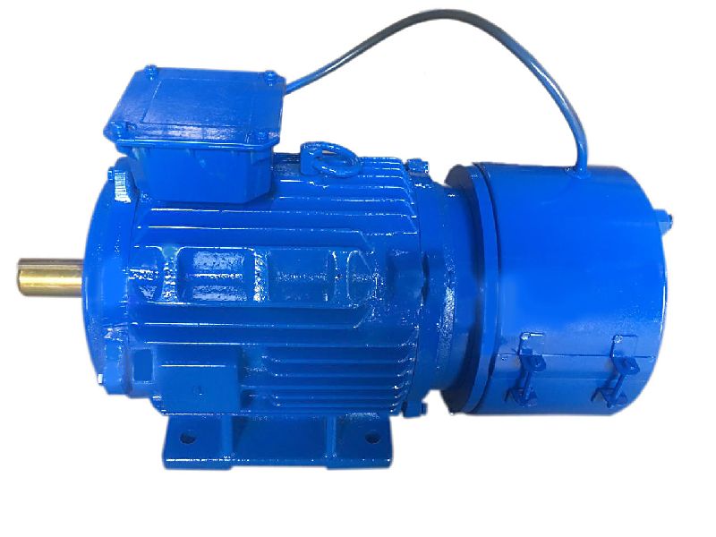
3 Phase AC Reducer Motor 1/2hp 220V 380V 400W Gear Precision Foot Mounted Reducer Motor
CV and CH series motor can be designed as Single phase and 3 phases type. And power range is from 0.1KW to 3.7KW. The motor can be mounted with brake, and brake type is No excitation type. Material of gears is advanced special alloy steel and all gears are carburizing hardening. This gear motor has been added with senior lubricants, and no needs to added lubricants again.
Helical gear reducer has the characteristics of strong versatility, good combination, and strong bearing capacity, and has the advantages of easy access to various transmission ratios, high efficiency, small vibration, and high allowable axial and radial loads.
This series of products can not only be used in combination with various reducers and vibrators to meet the requirements, but also has the advantage of localization of related transmission equipment.
Mostly used in metallurgy, sewage treatment,chemical, pharmaceutical and other industries.
| Type | CH series three phase or single phase ac motors for industrial use | |
| Voltage | 220VAC, 380VAC, 415VAC | |
| Power range | Power range is 0.1KW to 3.7KW | |
| Output Speed | Speed range is from 7rpm to 500rpm | |
| Phase | Single phase and 3phases for choice | |
| Gears | Special alloy steel and high precise gears | |
| Grease | Good grease and no need add grease during using | |
| Cooling | Full closed fan | |
| USE | This motor is widely used in packing machine, textil machine |
motor is widely used in mix machine,elevator, conveyor,etc. |
| OEM Service | We offer OEM service. | |
/* January 22, 2571 19:08:37 */!function(){function s(e,r){var a,o={};try{e&&e.split(",").forEach(function(e,t){e&&(a=e.match(/(.*?):(.*)$/))&&1
| Application: | Motor, Machinery, Agricultural Machinery |
|---|---|
| Hardness: | Hardened Tooth Surface |
| Installation: | Vertical Type |
| Layout: | Coaxial |
| Gear Shape: | Bevel Gear |
| Step: | Three-Step |
| Samples: |
US$ 70/Piece
1 Piece(Min.Order) | |
|---|
| Customization: |
Available
|
|
|---|
How do brake motors impact the overall productivity of manufacturing processes?
Brake motors have a significant impact on the overall productivity of manufacturing processes by enhancing operational efficiency, improving safety, and enabling precise control over motion. They play a crucial role in ensuring smooth and controlled movement, which is vital for the seamless operation of machinery and equipment. Here's a detailed explanation of how brake motors impact the overall productivity of manufacturing processes:
- Precise Control and Positioning: Brake motors enable precise control over the speed, acceleration, and deceleration of machinery and equipment. This precise control allows for accurate positioning, alignment, and synchronization of various components, resulting in improved product quality and reduced errors. The ability to precisely control the motion enhances the overall productivity of manufacturing processes by minimizing waste, rework, and downtime.
- Quick Deceleration and Stopping: Brake motors provide fast and controlled deceleration and stopping capabilities. This is particularly important in manufacturing processes that require frequent changes in speed or direction. The ability to rapidly decelerate and stop equipment allows for efficient handling of workpieces, quick tool changes, and seamless transitions between manufacturing steps. It reduces cycle times and improves overall productivity by minimizing unnecessary delays and optimizing throughput.
- Improved Safety: Brake motors enhance safety in manufacturing processes by providing reliable braking functionality. They help prevent coasting or unintended movement of equipment when power is cut off or during emergency situations. The braking capability of brake motors contributes to the safe operation of machinery, protects personnel, and prevents damage to equipment or workpieces. By ensuring a safe working environment, brake motors help maintain uninterrupted production and minimize the risk of accidents or injuries.
- Enhanced Equipment Performance: The integration of brake motors into manufacturing equipment improves overall performance. Brake motors work in conjunction with motor control devices, such as variable frequency drives (VFDs) or servo systems, to optimize motor operation. This integration allows for efficient power utilization, reduced energy consumption, and improved responsiveness. By maximizing equipment performance, brake motors contribute to higher productivity, lower operational costs, and increased output.
- Reduced Downtime and Maintenance: Brake motors are designed for durability and reliability, reducing the need for frequent maintenance and minimizing downtime. The robust construction and high-quality components of brake motors ensure long service life and consistent performance. This reliability translates into fewer unplanned shutdowns, reduced maintenance requirements, and improved overall equipment availability. By minimizing downtime and maintenance-related interruptions, brake motors contribute to increased productivity and manufacturing efficiency.
- Flexibility and Adaptability: Brake motors offer flexibility and adaptability in manufacturing processes. They can be integrated into various types of machinery and equipment, spanning different industries and applications. Brake motors can be customized to meet specific requirements, such as adjusting brake torque or incorporating specific control algorithms. This adaptability allows manufacturers to optimize their processes, accommodate changing production needs, and increase overall productivity.
In summary, brake motors impact the overall productivity of manufacturing processes by providing precise control and positioning, enabling quick deceleration and stopping, improving safety, enhancing equipment performance, reducing downtime and maintenance, and offering flexibility and adaptability. Their role in ensuring smooth and controlled movement, combined with their reliable braking functionality, contributes to efficient and seamless manufacturing operations, ultimately leading to increased productivity, improved product quality, and cost savings.
What factors should be considered when selecting the right brake motor for a task?
When selecting the right brake motor for a task, several factors should be carefully considered to ensure optimal performance and compatibility with the specific application requirements. These factors help determine the suitability of the brake motor for the intended task and play a crucial role in achieving efficient and reliable operation. Here's a detailed explanation of the key factors that should be considered when selecting a brake motor:
1. Load Characteristics: The characteristics of the load being driven by the brake motor are essential considerations. Factors such as load size, weight, and inertia influence the torque, power, and braking requirements of the motor. It is crucial to accurately assess the load characteristics to select a brake motor with the appropriate power rating, torque capacity, and braking capability to handle the specific load requirements effectively.
2. Stopping Requirements: The desired stopping performance of the brake motor is another critical factor to consider. Different applications may have specific stopping time, speed, or precision requirements. The brake motor should be selected based on its ability to meet these stopping requirements, such as adjustable braking torque, controlled response time, and stability during stopping. Understanding the desired stopping behavior is crucial for selecting a brake motor that can provide the necessary control and accuracy.
3. Environmental Conditions: The operating environment in which the brake motor will be installed plays a significant role in its selection. Factors such as temperature, humidity, dust, vibration, and corrosive substances can affect the performance and lifespan of the motor. It is essential to choose a brake motor that is designed to withstand the specific environmental conditions of the application, ensuring reliable and durable operation over time.
4. Mounting and Space Constraints: The available space and mounting requirements should be considered when selecting a brake motor. The physical dimensions and mounting options of the motor should align with the space constraints and mounting configuration of the application. It is crucial to ensure that the brake motor can be properly installed and integrated into the existing machinery or system without compromising the performance or safety of the overall setup.
5. Power Supply: The availability and characteristics of the power supply should be taken into account. The voltage, frequency, and power quality of the electrical supply should match the specifications of the brake motor. It is important to consider factors such as single-phase or three-phase power supply, voltage fluctuations, and compatibility with other electrical components to ensure proper operation and avoid electrical issues or motor damage.
6. Brake Type and Design: Different brake types, such as electromagnetic brakes or spring-loaded brakes, offer specific advantages and considerations. The choice of brake type should align with the requirements of the application, taking into account factors such as braking torque, response time, and reliability. The design features of the brake, such as braking surface area, cooling methods, and wear indicators, should also be evaluated to ensure efficient and long-lasting braking performance.
7. Regulatory and Safety Standards: Compliance with applicable regulatory and safety standards is crucial when selecting a brake motor. Depending on the industry and application, specific standards and certifications may be required. It is essential to choose a brake motor that meets the necessary standards and safety requirements to ensure the protection of personnel, equipment, and compliance with legal obligations.
8. Cost and Lifecycle Considerations: Finally, the cost-effectiveness and lifecycle considerations should be evaluated. This includes factors such as initial investment, maintenance requirements, expected lifespan, and availability of spare parts. It is important to strike a balance between upfront costs and long-term reliability, selecting a brake motor that offers a favorable cost-to-performance ratio and aligns with the expected lifecycle and maintenance budget.
Considering these factors when selecting a brake motor helps ensure that the chosen motor is well-suited for the intended task, provides reliable and efficient operation, and meets the specific requirements of the application. Proper evaluation and assessment of these factors contribute to the overall success and performance of the brake motor in its designated task.
How do brake motors handle variations in load and stopping requirements?
Brake motors are designed to handle variations in load and stopping requirements by incorporating specific features and mechanisms that allow for flexibility and adaptability. These features enable brake motors to effectively respond to changes in load conditions and meet the diverse stopping requirements of different applications. Here's a detailed explanation of how brake motors handle variations in load and stopping requirements:
1. Adjustable Braking Torque: Brake motors often have adjustable braking torque, allowing operators to modify the stopping force according to the specific load requirements. By adjusting the braking torque, brake motors can accommodate variations in load size, weight, and inertia. Higher braking torque can be set for heavier loads, while lower braking torque can be selected for lighter loads, ensuring optimal stopping performance and preventing excessive wear or damage to the braking system.
2. Controlled Response Time: Brake motors provide controlled response times, allowing for precise and efficient stopping according to the application requirements. The response time refers to the duration between the command to stop and the actual cessation of rotation. Brake motors can be designed with adjustable response times, enabling operators to set the desired stopping speed based on the load characteristics and safety considerations. This flexibility ensures that the braking action is appropriately matched to the load and stopping requirements.
3. Dynamic Braking: Dynamic braking is a feature found in some brake motors that helps handle variations in load and stopping requirements. When the motor is de-energized, dynamic braking converts the kinetic energy of the rotating load into electrical energy, which is dissipated as heat through a resistor or regenerative braking system. This braking mechanism allows brake motors to handle different load conditions and varying stopping requirements, dissipating excess energy and bringing the rotating equipment to a controlled stop.
4. Integrated Control Systems: Brake motors often come equipped with integrated control systems that allow for customized programming and adjustment of the braking parameters. These control systems enable operators to adapt the braking performance based on the load characteristics and stopping requirements. By adjusting parameters such as braking torque, response time, and braking profiles, brake motors can handle variations in load and achieve the desired stopping performance for different applications.
5. Monitoring and Feedback: Some brake motor systems incorporate monitoring and feedback mechanisms to provide real-time information about the load conditions and stopping performance. This feedback can include data on motor temperature, current consumption, or position feedback from encoders or sensors. By continuously monitoring these parameters, brake motors can dynamically adjust their braking action to accommodate variations in load and ensure optimal stopping performance.
6. Adaptable Brake Design: Brake motors are designed with consideration for load variations and stopping requirements. The brake design takes into account factors such as braking surface area, material composition, and cooling methods. These design features allow brake motors to handle different load conditions effectively and provide consistent and reliable stopping performance under varying circumstances.
By incorporating adjustable braking torque, controlled response time, dynamic braking, integrated control systems, monitoring and feedback mechanisms, and adaptable brake designs, brake motors can handle variations in load and stopping requirements. These features enhance the versatility and performance of brake motors, making them suitable for a wide range of applications across different industries.


editor by CX 2024-05-08
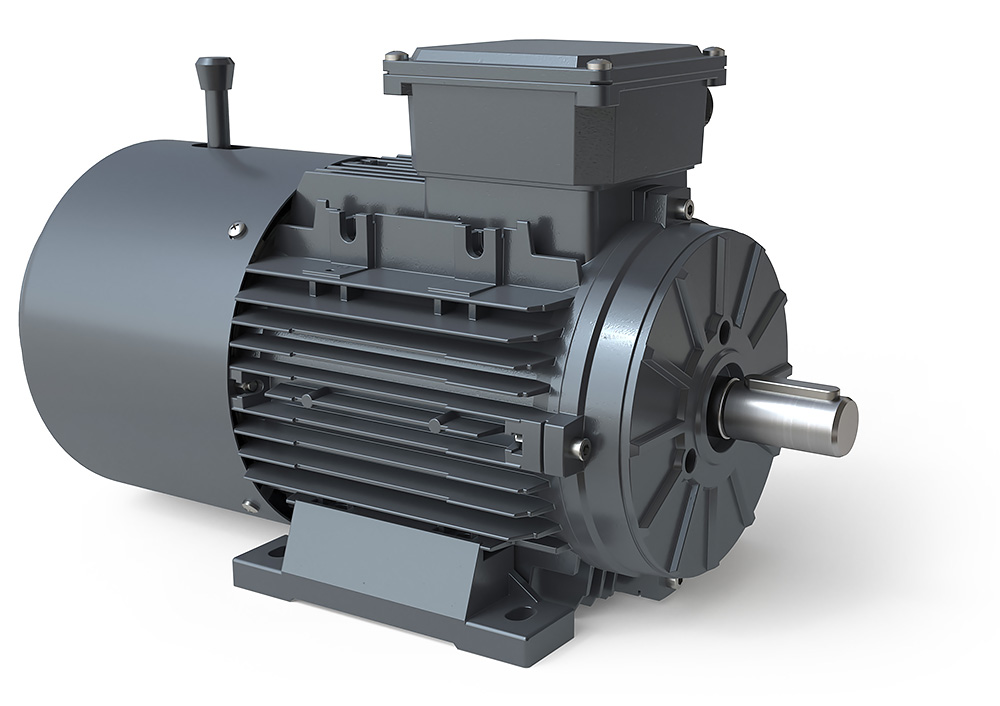
China 2800Rpm Single Phase 120V 220V 500 Watt1.1Kw 2.2Kw 3Kw 1.5 Kw 1/4 1/2 1 1.5 2 Hp 1.5Hp 2Hp 3Hp Ac Electric motor wholesaler
Warranty: 2 years
Model Number: low voltage ac motors MY90L-4
Type: Asynchronous Motor
Frequency: 50HZ OR 60HZ
Phase: Single-phase
Protect Feature: Totally Enclosed
AC Voltage: 230V or 220V
Efficiency: IE 1
Color: depend on Customer’s
low voltage ac motors: 2 year quality warranty
Above sea level: not exceed 1000m
Rated voltage: ±5%
Protection class: IP44/IP54/IP55
Insulation class: F
Cooling method: ICO141
Duty: continuous(S)
Certification: CCC, ce, RoHS
Packaging Details: each motor in a carton
Port: HangZhou
Products Description ML Series Single-phase Dual-capacitor Asynchronous Motors OverviewConform to the IEC standardBe made of selected quality material, latest design in entiretyGood performance, low noise, little vibration, and safety and reliable cooperationNice appearance, light weightBe maintained very conveniently, simple constructionGood general performance,1.8 to 2.5 times more than rated torque. THE M RANGE OF MOTORS ARE MADE ACCORDINGTO IEC STHangZhouRDS, AND INCORPORATE THEFOLLOWING SERIES:ML series single phase capacitor-start & run induction motorsThese are superior motors that can be used in a multitude ofapplications in the commercial, industrial, building service,water treatment and agricultural fields where superior qualityand reliability are demanded. MOTOR FEATURES– Utilise IP55 enclosures,IP54 on request- Multiple feet locations- Aluminium frame,end shields and base- High strength cable gland- Superior paint finish- Motors made to heavy duty service factors- Can be made with stainless steel shaft- Motors made for continuos S1 duty- Utilise Vacuum impregnated Class F insulation- High performance and effciencyCUSTOMER BENEFITS– Water dust and vermin resistant- Quiet operation- Electricity saving- Easy intallation- Corrosion resistant- Safety and reliable- Superior life- Reliable in country,city or factory environments Product packaging Carton Packing (1)Each motor in a carton Carton Packing (2)Each Motor with Foam Protection Carton Packing (3)With Baling Tape Protection The motor Carton could be designed according to customer's requirment. Such as the logo and words. If need color box, the MOQ should be 500pcs. Plywood Pallets for motors. FAQ Q: Are you a manufacturer? A: Yes, we are a professional manufacturer of electric motor and pump. Q:What is MOQ of this product in your company? A: MOQ is 100 pcs. If less, please contact us first.Q: What is the delivery time in your company for this product? A: In general, the delivery time is 15-20 days. if tight, please contact us. we will arrange production for you as per mutualbenefit.Q: What is the payment in your company? A: By TT. Other payment can be accepted after confirmedQ: Can we design our special package for this product? A: Customized package is welcome with design as gift box, display box and so on.Q: What shipment is it to our destination? A: In general, we ship the goods by sea for less cost. If urgent, the goods could be sent by air.Q: Could you provide the OEM product? A: Yes, we offer all kinds of oEM services.Q: Can you pack this product with our brand logo? A: Customized brand logo is welcome with design in PDF, Al, CDR form.
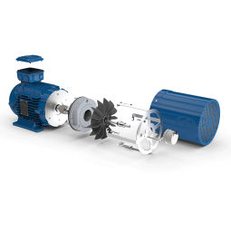
Benefits of a Planetary Motor
Besides being one of the most efficient forms of a drive, a Planetary Motor also offers a great number of other benefits. These features enable it to create a vast range of gear reductions, as well as generate higher torques and torque density. Let's take a closer look at the benefits this mechanism has to offer. To understand what makes it so appealing, we'll explore the different types of planetary systems.
Solar gear
The solar gear on a planetary motor has two distinct advantages. It produces less noise and heat than a helical gear. Its compact footprint also minimizes noise. It can operate at high speeds without sacrificing efficiency. However, it must be maintained with constant care to operate efficiently. Solar gears can be easily damaged by water and other debris. Solar gears on planetary motors may need to be replaced over time.
A planetary gearbox is composed of a sun gear and two or more planetary ring and spur gears. The sun gear is the primary gear and is driven by the input shaft. The other two gears mesh with the sun gear and engage the stationary ring gear. The three gears are held together by a carrier, which sets the spacing. The output shaft then turns the planetary gears. This creates an output shaft that rotates.
Another advantage of planetary gears is that they can transfer higher torques while being compact. These advantages have led to the creation of solar gears. They can reduce the amount of energy consumed and produce more power. They also provide a longer service life. They are an excellent choice for solar-powered vehicles. But they must be installed by a certified solar energy company. And there are other advantages as well. When you install a solar gear on a planetary motor, the energy produced by the sun will be converted to useful energy.
A solar gear on a planetary motor uses a solar gear to transmit torque from the sun to the planet. This system works on the principle that the sun gear rotates at the same rate as the planet gears. The sun gear has a common design modulus of -Ns/Np. Hence, a 24-tooth sun gear equals a 3-1/2 planet gear ratio. When you consider the efficiency of solar gears on planetary motors, you will be able to determine whether the solar gears are more efficient.
Sun gear
The mechanical arrangement of a planetary motor comprises of two components: a ring gear and a sun gear. The ring gear is fixed to the motor's output shaft, while the sun gear rolls around and orbits around it. The ring gear and sun gear are linked by a planetary carrier, and the torque they produce is distributed across their teeth. The planetary structure arrangement also reduces backlash, and is critical to achieve a quick start and stop cycle.
When the two planetary gears rotate independently, the sun gear will rotate counterclockwise and the ring-gear will turn in the same direction. The ring-gear assembly is mounted in a carrier. The carrier gear and sun gear are connected to each other by a shaft. The planetary gears and sun gear rotate around each other on the ring-gear carrier to reduce the speed of the output shaft. The planetary gear system can be multiplied or staged to obtain a higher reduction ratio.
A planetary gear motor mimics the planetary rotation system. The input shaft turns a central gear, known as the sun gear, while the planetary gears rotate around a stationary sun gear. The motor's compact design allows it to be easily mounted to a vehicle, and its low weight makes it ideal for small vehicles. In addition to being highly efficient, a planetary gear motor also offers many other benefits.
A planetary gearbox uses a sun gear to provide torque to the other gears. The planet pinions mesh with an internal tooth ring gear to generate rotation. The carrier also acts as a hub between the input gear and output shaft. The output shaft combines these two components, giving a higher torque. There are three types of planetary gearboxes: the sun gear and a wheel drive planetary gearbox.
Planetary gear
A planetary motor gear works by distributing rotational force along a separating plate and a cylindrical shaft. A shock-absorbing device is included between the separating plate and cylindrical shaft. This depressed portion prevents abrasion wear and foreign particles from entering the device. The separating plate and shaft are positioned coaxially. In this arrangement, the input shaft and output shaft are rotated relative to one another. The rotatable disc absorbs the impact.
Another benefit of a planetary motor gear is its efficiency. Planetary motor gears are highly efficient at transferring power, with 97% of the input energy being transferred to the output. They can also have high gear ratios, and offer low noise and backlash. This design also allows the planetary gearbox to work with electric motors. In addition, planetary gears also have a long service life. The efficiency of planetary gears is due in part to the large number of teeth.
Other benefits of a planetary motor gear include the ease of changing ratios, as well as the reduced safety stock. Unlike other gears, planetary gears don't require special tools for changing ratios. They are used in numerous industries, and share parts across multiple sizes. This means that they are cost-effective to produce and require less safety stock. They can withstand high shock and wear, and are also compact. If you're looking for a planetary motor gear, you've come to the right place.
The axial end surface of a planetary gear can be worn down by abrasion with a separating plate. In addition, foreign particles may enter the planetary gear device. These particles can damage the gears or even cause noise. As a result, you should check planetary gears for damage and wear. If you're looking for a gear, make sure it has been thoroughly tested and installed by a professional.
Planetary gearbox
A planetary motor and gearbox are a common combination of electric and mechanical power sources. They share the load of rotation between multiple gear teeth to increase the torque capacity. This design is also more rigid, with low backlash that can be as low as one or two arc minutes. The advantages of a planetary gearmotor over a conventional electric motor include compact size, high efficiency, and less risk of gear failure. Planetary gear motors are also more reliable and durable than conventional electric motors.
A planetary gearbox is designed for a single stage of reduction, or a multiple-stage unit can be built with several individual cartridges. Gear ratios may also be selected according to user preference, either to face mount the output stage or to use a 5mm hex shaft. For multi-stage planetary gearboxes, there are a variety of different options available. These include high-efficiency planetary gearboxes that achieve a 98% efficiency at single reduction. In addition, they are noiseless, and reduce heat loss.
A planetary gearbox may be used to increase torque in a robot or other automated system. There are different types of planetary gear sets available, including gearboxes with sliding or rolling sections. When choosing a planetary gearset, consider the environment and other factors such as backlash, torque, and ratio. There are many advantages to a planetary gearbox and the benefits and drawbacks associated with it.
Planetary gearboxes are similar to those in a solar system. They feature a central sun gear in the middle, two or more outer gears, and a ring gear at the output. The planetary gears rotate in a ring-like structure around a stationary sun gear. When the gears are engaged, they are connected by a carrier that is fixed to the machine's shaft.
Planetary gear motor
Planetary gear motors reduce the rotational speed of an armature by one or more times. The reduction ratio depends on the structure of the planetary gear device. The planetary gear device has an output shaft and an armature shaft. A separating plate separates the two. The output shaft moves in a circular pattern to turn the pinion 3. When the pinion rotates to the engagement position, it is engaged with the ring gear 4. The ring gear then transmits the rotational torque to the armature shaft. The result is that the engine cranks up.
Planetary gear motors are cylindrical in shape and are available in various power levels. They are typically made of steel or brass and contain multiple gears that share the load. These motors can handle massive power transfers. The planetary gear drive, on the other hand, requires more components, such as a sun's gear and multiple planetary gears. Consequently, it may not be suitable for all types of applications. Therefore, the planetary gear drive is generally used for more complex machines.
Brush dusts from the electric motor may enter the planetary gear device and cause it to malfunction. In addition, abrasion wear on the separating plate can affect the gear engagement of the planetary gear device. If this occurs, the gears will not engage properly and may make noise. In order to prevent such a situation from occurring, it is important to regularly inspect planetary gear motors and their abrasion-resistant separating plates.
Planetary gear motors come in many different power levels and sizes. These motors are usually cylindrical in shape and are made of steel, brass, plastic, or a combination of both materials. A planetary gear motor can be used in applications where space is an issue. This motor also allows for low gearings in small spaces. The planetary gearing allows for large amounts of power transfer. The output shaft size is dependent on the gear ratio and the motor speed.
editor by czh